HP Z200 HP Z200 SFF Workstation Maintenance and Service Guide - Page 92
Carefully handle hard disk drives, Removing an optical drive, CAUTION - small form factor
 |
View all HP Z200 manuals
Add to My Manuals
Save this manual to your list of manuals |
Page 92 highlights
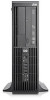
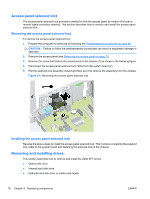
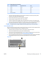
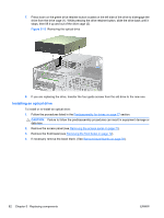
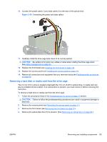
Table 5-6 Extra Guide Screw Locations No. Guide screw, color Device 1 Black M3 Metric Screws Optical disk drives, SSDs, small form factor hard drives (6.3cm/2.5in), media card reader 2 Silver 6-32 Standard Screws 8.9cm/3.5in hard disk drives, front bezel security There are at total of five extra silver 6-32 standard screws. Four are used as guide screws for a secondary hard drive. The fifth is used for bezel security. Carefully handle hard disk drives CAUTION: Take proper precautions when handling hard disk drives to prevent loss of work and damage to the computer or drive. ● Always follow the Predisassembly procedures on page 68, which include shutting down the operating system, turning off the power, and unplugging the power cord. Never remove a drive while the computer is on or in standby mode. ● Before handling a drive, ensure that you are discharged of static electricity. While handling a drive, avoid touching the connector. ● Handle a drive carefully; do not drop it. ● Do not use excessive force when inserting a drive. ● Avoid exposing a hard drive to liquids, temperature extremes, or products that have magnetic fields such as monitors or speakers. ● If you must mail a drive, use a bubble-pack mailer or other protective packaging and label the package "Fragile: Handle With Care." Removing an optical drive To remove an optical drive from the drive cage: 1. Follow the procedures listed in the Predisassembly for drives on page 77 section. CAUTION: Failure to follow the predisassembly procedures can result in equipment damage or data loss. 2. Remove the access panel (see Removing the access panel on page 71). 3. Remove the front bezel (see Removing the front bezel on page 72). 80 Chapter 5 Replacing components ENWW
-
 1
1 -
2
-
3
-
4
-
5
-
6
-
7
-
8
-
9
-
10
-
11
-
12
-
13
-
14
-
15
-
16
-
17
-
18
-
19
-
20
-
21
-
22
-
23
-
24
-
25
-
26
-
27
-
28
-
29
-
30
-
31
-
32
-
33
-
34
-
35
-
36
-
37
-
38
-
39
-
40
-
41
-
42
-
43
-
44
-
45
-
46
-
47
-
48
-
49
-
50
-
51
-
52
-
53
-
54
-
55
-
56
-
57
-
58
-
59
-
60
-
61
-
62
-
63
-
64
-
65
-
66
-
67
-
68
-
69
-
70
-
71
-
72
-
73
-
74
-
75
-
76
-
77
-
78
-
79
-
80
-
81
-
82
-
83
-
84
-
85
-
86
-
 87
87 -
 88
88 -
 89
89 -
 90
90 -
 91
91 -
 92
92 -
 93
93 -
 94
94 -
 95
95 -
 96
96 -
 97
97 -
98
-
99
-
100
-
101
-
102
-
103
-
104
-
105
-
106
-
107
-
108
-
109
-
110
-
111
-
112
-
113
-
114
-
115
-
116
-
117
-
118
-
119
-
120
-
121
-
122
-
123
-
124
-
125
-
126
-
127
-
128
-
129
-
130
-
131
-
132
-
133
-
134
-
135
-
136
-
137
-
138
-
139
-
140
-
141
-
142
-
143
-
144
-
145
-
146
-
147
-
148
-
149
-
150
-
151
-
152
-
153
-
154
-
155
-
156
-
157
-
158
-
159
-
160
-
161
-
162
-
163
-
164
-
165
-
166
-
167
-
168
-
169
-
170
-
171
-
172
-
173
-
174
-
175
-
176
-
177
-
178
-
179
-
180
-
181
-
182
-
183
-
184
-
185
-
186
-
187
-
188
-
189
-
190
-
191
-
192
-
193
-
194
-
195
-
196
-
197
-
198
-
199
 |
 |