HP Z200 HP Z200 SFF Workstation Maintenance and Service Guide - Page 91
Locate extra guide screws, System Board Drive Connections
 |
View all HP Z200 manuals
Add to My Manuals
Save this manual to your list of manuals |
Page 91 highlights
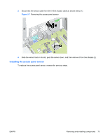
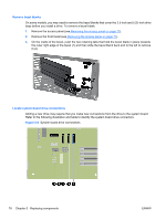
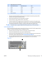
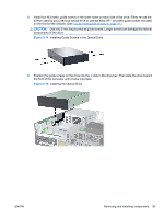
Table 5-5 System Board Drive Connections No. System Board Connector System Board Label 1 SATA0 SATA0 2 SATA1 SATA1 3 SATA2 SATA2 4 eSATA eSATA 5 Media Card Reader MEDIA Color dark blue black black black black ● The primary Serial ATA (SATA) hard drive must be connected to the dark blue primary SATA connector on the system board labeled SATA0. ● Connect SATA optical drives to the white SATA1 connector. ● Connect devices in order of SATA0, SATA1, then SATA2 ● Connect an optional eSATA adapter cable to the black ESATA connector on the system board. ● Connect a media card reader USB cable to the USB connector on the system board labeled MEDIA. If the media card reader has a 1394 port, connect the 1394 cable to the 1394 PCI card. NOTE: The system does not support Parallel ATA (PATA) optical drives or PATA hard drives. Locate extra guide screws Each drive requires four guide screws to ensure the drive lines up correctly in the drive cage and locks in place. HP provides extra guide screws for installing new drives. ● The extra screws are mounted in the front of the chassis, under the front bezel. ● There are four black M3 metric screws used to install most drives. ● There are five silver 6-32 standard screws. Four are used for mounting 3.5-inch hard disk drives, and the fifth is used for bezel security (see Front bezel security on page 73). ● If you are replacing the primary hard drive, you must remove the four silver and blue 6-32 isolation mounting guide screws from the old hard drive and install them in the new hard drive. Figure 5-10 ENWW Removing and installing components 79
-
 1
1 -
2
-
3
-
4
-
5
-
6
-
7
-
8
-
9
-
10
-
11
-
12
-
13
-
14
-
15
-
16
-
17
-
18
-
19
-
20
-
21
-
22
-
23
-
24
-
25
-
26
-
27
-
28
-
29
-
30
-
31
-
32
-
33
-
34
-
35
-
36
-
37
-
38
-
39
-
40
-
41
-
42
-
43
-
44
-
45
-
46
-
47
-
48
-
49
-
50
-
51
-
52
-
53
-
54
-
55
-
56
-
57
-
58
-
59
-
60
-
61
-
62
-
63
-
64
-
65
-
66
-
67
-
68
-
69
-
70
-
71
-
72
-
73
-
74
-
75
-
76
-
77
-
78
-
79
-
80
-
81
-
82
-
83
-
84
-
85
-
 86
86 -
 87
87 -
 88
88 -
 89
89 -
 90
90 -
 91
91 -
 92
92 -
 93
93 -
 94
94 -
 95
95 -
 96
96 -
97
-
98
-
99
-
100
-
101
-
102
-
103
-
104
-
105
-
106
-
107
-
108
-
109
-
110
-
111
-
112
-
113
-
114
-
115
-
116
-
117
-
118
-
119
-
120
-
121
-
122
-
123
-
124
-
125
-
126
-
127
-
128
-
129
-
130
-
131
-
132
-
133
-
134
-
135
-
136
-
137
-
138
-
139
-
140
-
141
-
142
-
143
-
144
-
145
-
146
-
147
-
148
-
149
-
150
-
151
-
152
-
153
-
154
-
155
-
156
-
157
-
158
-
159
-
160
-
161
-
162
-
163
-
164
-
165
-
166
-
167
-
168
-
169
-
170
-
171
-
172
-
173
-
174
-
175
-
176
-
177
-
178
-
179
-
180
-
181
-
182
-
183
-
184
-
185
-
186
-
187
-
188
-
189
-
190
-
191
-
192
-
193
-
194
-
195
-
196
-
197
-
198
-
199
 |
 |