HP Z200 HP Z200 SFF Workstation Maintenance and Service Guide - Page 95
CAUTION, Installing Guide Screws in the Optical Drive
 |
View all HP Z200 manuals
Add to My Manuals
Save this manual to your list of manuals |
Page 95 highlights
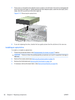
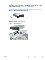
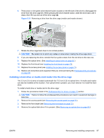
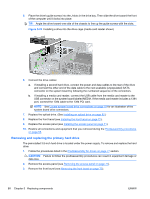
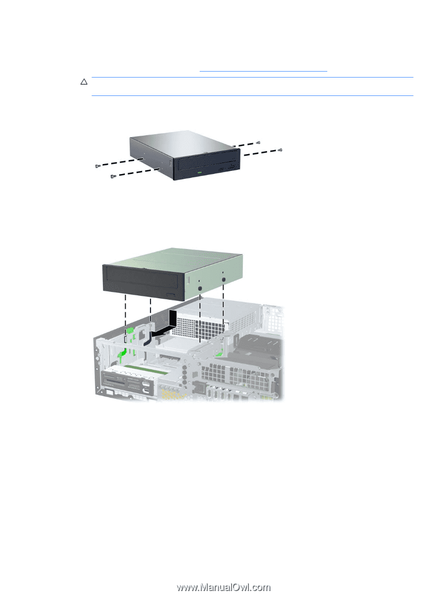
5. Install four M3 metric guide screws in the lower holes on each side of the drive. Either re-use the screws used by your previous optical drive or use the extra HP-provided guide screws mounted on the front of the chassis. (See Locate extra guide screws on page 79.) CAUTION: Use only 5-mm long screws as guide screws. Longer screws can damage the internal components of the drive. Figure 5-14 Installing Guide Screws in the Optical Drive 6. Position the guide screws on the drive into the J-slots in the drive bay. Then slide the drive toward the front of the computer until it locks into place. Figure 5-15 Installing the Optical Drive ENWW Removing and installing components 83
-
 1
1 -
2
-
3
-
4
-
5
-
6
-
7
-
8
-
9
-
10
-
11
-
12
-
13
-
14
-
15
-
16
-
17
-
18
-
19
-
20
-
21
-
22
-
23
-
24
-
25
-
26
-
27
-
28
-
29
-
30
-
31
-
32
-
33
-
34
-
35
-
36
-
37
-
38
-
39
-
40
-
41
-
42
-
43
-
44
-
45
-
46
-
47
-
48
-
49
-
50
-
51
-
52
-
53
-
54
-
55
-
56
-
57
-
58
-
59
-
60
-
61
-
62
-
63
-
64
-
65
-
66
-
67
-
68
-
69
-
70
-
71
-
72
-
73
-
74
-
75
-
76
-
77
-
78
-
79
-
80
-
81
-
82
-
83
-
84
-
85
-
86
-
87
-
88
-
89
-
 90
90 -
 91
91 -
 92
92 -
 93
93 -
 94
94 -
 95
95 -
 96
96 -
 97
97 -
 98
98 -
 99
99 -
 100
100 -
101
-
102
-
103
-
104
-
105
-
106
-
107
-
108
-
109
-
110
-
111
-
112
-
113
-
114
-
115
-
116
-
117
-
118
-
119
-
120
-
121
-
122
-
123
-
124
-
125
-
126
-
127
-
128
-
129
-
130
-
131
-
132
-
133
-
134
-
135
-
136
-
137
-
138
-
139
-
140
-
141
-
142
-
143
-
144
-
145
-
146
-
147
-
148
-
149
-
150
-
151
-
152
-
153
-
154
-
155
-
156
-
157
-
158
-
159
-
160
-
161
-
162
-
163
-
164
-
165
-
166
-
167
-
168
-
169
-
170
-
171
-
172
-
173
-
174
-
175
-
176
-
177
-
178
-
179
-
180
-
181
-
182
-
183
-
184
-
185
-
186
-
187
-
188
-
189
-
190
-
191
-
192
-
193
-
194
-
195
-
196
-
197
-
198
-
199
 |
 |
5.
Install four M3 metric guide screws in the lower holes on each side of the drive. Either re-use the
screws used by your previous optical drive or use the extra HP—provided guide screws mounted
on the front of the chassis. (See
Locate extra guide screws
on page
79
.)
CAUTION:
Use only 5-mm long screws as guide screws. Longer screws can damage the internal
components of the drive.
Figure 5-14
Installing Guide Screws in the Optical Drive
6.
Position the guide screws on the drive into the J-slots in the drive bay. Then slide the drive toward
the front of the computer until it locks into place.
Figure 5-15
Installing the Optical Drive
ENWW
Removing and installing components
83