HP Z200 HP Z200 SFF Workstation Maintenance and Service Guide - Page 111
Replace the access panel see
 |
View all HP Z200 manuals
Add to My Manuals
Save this manual to your list of manuals |
Page 111 highlights
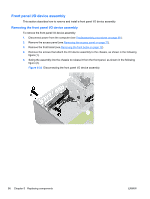
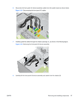
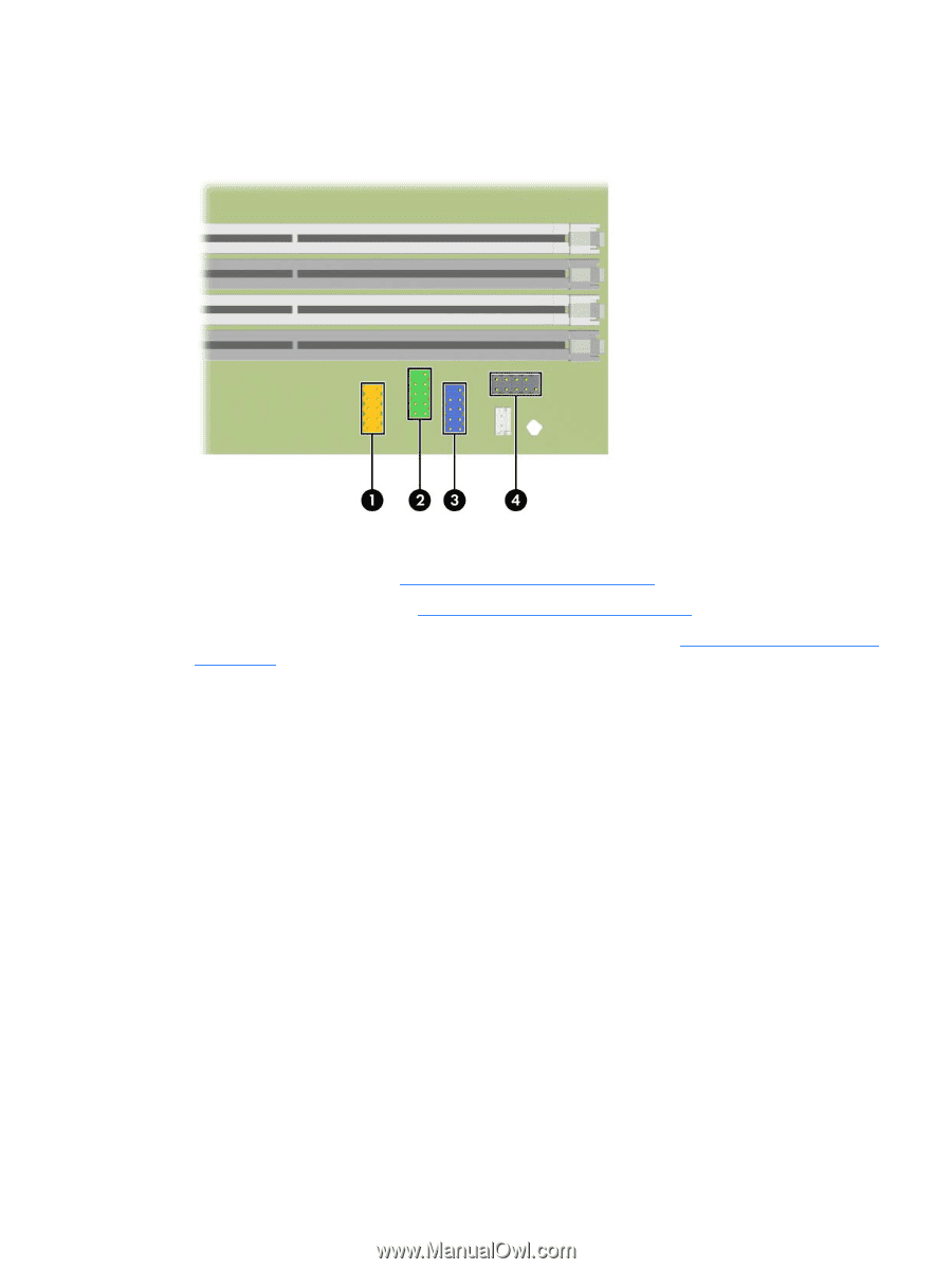
7. Connect the front panel USB (1 and 2), front audio (3), and front power/LED (4) cables to the system board as shown in the following diagram. Figure 5-37 Connecting the front panel I/O device cables 8. Rotate the drive cage down to its normal position. 9. Replace the front bezel (see Installing the front bezel on page 72). 10. Replace the access panel (see Installing the access panel on page 71). 11. Restore all connections and equipment that you removed during the Predisassembly procedures on page 68. ENWW Removing and installing components 99
-
 1
1 -
2
-
3
-
4
-
5
-
6
-
7
-
8
-
9
-
10
-
11
-
12
-
13
-
14
-
15
-
16
-
17
-
18
-
19
-
20
-
21
-
22
-
23
-
24
-
25
-
26
-
27
-
28
-
29
-
30
-
31
-
32
-
33
-
34
-
35
-
36
-
37
-
38
-
39
-
40
-
41
-
42
-
43
-
44
-
45
-
46
-
47
-
48
-
49
-
50
-
51
-
52
-
53
-
54
-
55
-
56
-
57
-
58
-
59
-
60
-
61
-
62
-
63
-
64
-
65
-
66
-
67
-
68
-
69
-
70
-
71
-
72
-
73
-
74
-
75
-
76
-
77
-
78
-
79
-
80
-
81
-
82
-
83
-
84
-
85
-
86
-
87
-
88
-
89
-
90
-
91
-
92
-
93
-
94
-
95
-
96
-
97
-
98
-
99
-
100
-
101
-
102
-
103
-
104
-
105
-
 106
106 -
 107
107 -
 108
108 -
 109
109 -
 110
110 -
 111
111 -
 112
112 -
 113
113 -
 114
114 -
 115
115 -
 116
116 -
117
-
118
-
119
-
120
-
121
-
122
-
123
-
124
-
125
-
126
-
127
-
128
-
129
-
130
-
131
-
132
-
133
-
134
-
135
-
136
-
137
-
138
-
139
-
140
-
141
-
142
-
143
-
144
-
145
-
146
-
147
-
148
-
149
-
150
-
151
-
152
-
153
-
154
-
155
-
156
-
157
-
158
-
159
-
160
-
161
-
162
-
163
-
164
-
165
-
166
-
167
-
168
-
169
-
170
-
171
-
172
-
173
-
174
-
175
-
176
-
177
-
178
-
179
-
180
-
181
-
182
-
183
-
184
-
185
-
186
-
187
-
188
-
189
-
190
-
191
-
192
-
193
-
194
-
195
-
196
-
197
-
198
-
199
 |
 |
7.
Connect the front panel USB (1 and 2), front audio (3), and front power/LED (4) cables to the system
board as shown in the following diagram.
Figure 5-37
Connecting the front panel I/O device cables
8.
Rotate the drive cage down to its normal position.
9.
Replace the front bezel (see
Installing the front bezel
on page
72
).
10.
Replace the access panel (see
Installing the access panel
on page
71
).
11.
Restore all connections and equipment that you removed during the
Predisassembly procedures
on page
68
.
ENWW
Removing and installing components
99