HP Z200 HP Z200 SFF Workstation Maintenance and Service Guide - Page 78
Removing and installing components, Component locations
 |
View all HP Z200 manuals
Add to My Manuals
Save this manual to your list of manuals |
Page 78 highlights
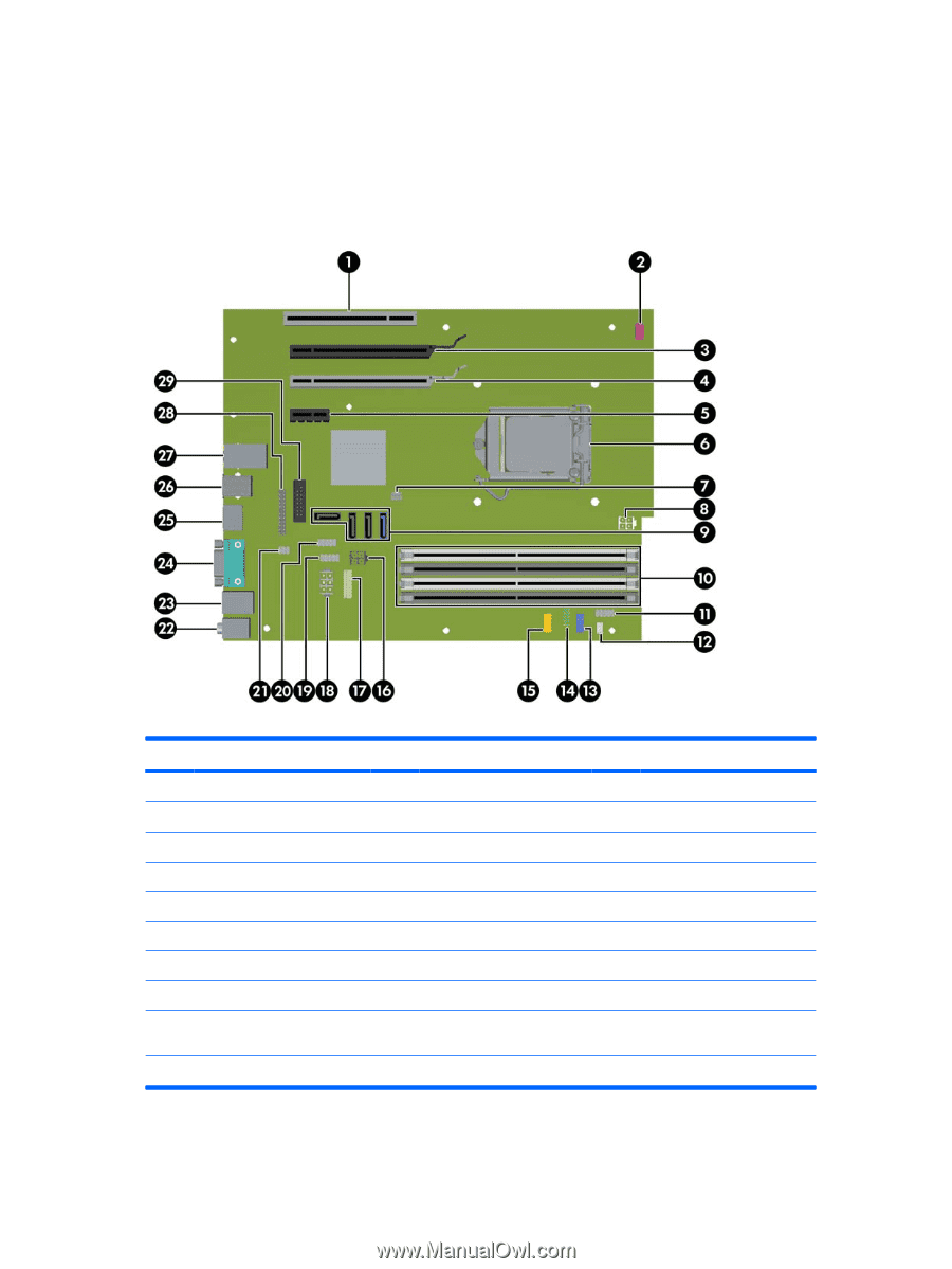
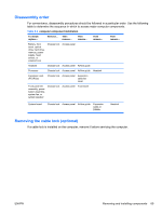
Removing and installing components Component locations The following illustration and table identify computer system board components. Figure 5-1 System board component locations Table 5-2 System board components ID Item Component Item Component Item Component 1 PCI 32/33 11 Front power button/LED 21 Solenoid hood lock 2 Front system fan 12 Speaker 22 Audio 3 PCIe2 x16(16) 13 Front audio 23 Keyboard/mouse 4 PCIe x16(4) 14 Front USB 24 VGA/1st serial 5 PCIe x1 15 Front USB 25 Display port 6 CPU socket 16 SATA power 26 USB 7 Chassis intrusion switch 17 Power COMM 27 Network/USB 8 CPU power 18 Main power 28 Parallel 9 SATA ports (3) and eSATA port (1) 19 Internal USB1 29 2nd serial 10 Memory sockets 20 Internal USB2/DASH All SATA ports are eSATA compatible, even though only one port is labeled for eSATA on the system board. The DP and VGA ports are disabled if used with Intel Xeon quad-core processors. 66 Chapter 5 Replacing components ENWW
-
 1
1 -
2
-
3
-
4
-
5
-
6
-
7
-
8
-
9
-
10
-
11
-
12
-
13
-
14
-
15
-
16
-
17
-
18
-
19
-
20
-
21
-
22
-
23
-
24
-
25
-
26
-
27
-
28
-
29
-
30
-
31
-
32
-
33
-
34
-
35
-
36
-
37
-
38
-
39
-
40
-
41
-
42
-
43
-
44
-
45
-
46
-
47
-
48
-
49
-
50
-
51
-
52
-
53
-
54
-
55
-
56
-
57
-
58
-
59
-
60
-
61
-
62
-
63
-
64
-
65
-
66
-
67
-
68
-
69
-
70
-
71
-
72
-
 73
73 -
 74
74 -
 75
75 -
 76
76 -
 77
77 -
 78
78 -
 79
79 -
 80
80 -
 81
81 -
 82
82 -
 83
83 -
84
-
85
-
86
-
87
-
88
-
89
-
90
-
91
-
92
-
93
-
94
-
95
-
96
-
97
-
98
-
99
-
100
-
101
-
102
-
103
-
104
-
105
-
106
-
107
-
108
-
109
-
110
-
111
-
112
-
113
-
114
-
115
-
116
-
117
-
118
-
119
-
120
-
121
-
122
-
123
-
124
-
125
-
126
-
127
-
128
-
129
-
130
-
131
-
132
-
133
-
134
-
135
-
136
-
137
-
138
-
139
-
140
-
141
-
142
-
143
-
144
-
145
-
146
-
147
-
148
-
149
-
150
-
151
-
152
-
153
-
154
-
155
-
156
-
157
-
158
-
159
-
160
-
161
-
162
-
163
-
164
-
165
-
166
-
167
-
168
-
169
-
170
-
171
-
172
-
173
-
174
-
175
-
176
-
177
-
178
-
179
-
180
-
181
-
182
-
183
-
184
-
185
-
186
-
187
-
188
-
189
-
190
-
191
-
192
-
193
-
194
-
195
-
196
-
197
-
198
-
199
 |
 |