Netgear FS752TPS FS752TS Setup Manual - Page 157
Server Log, REFRESH, CLEAR, Monitoring > Logs > Server Log, Server, UDP Port, Facility
 |
View all Netgear FS752TPS manuals
Add to My Manuals
Save this manual to your list of manuals |
Page 157 highlights
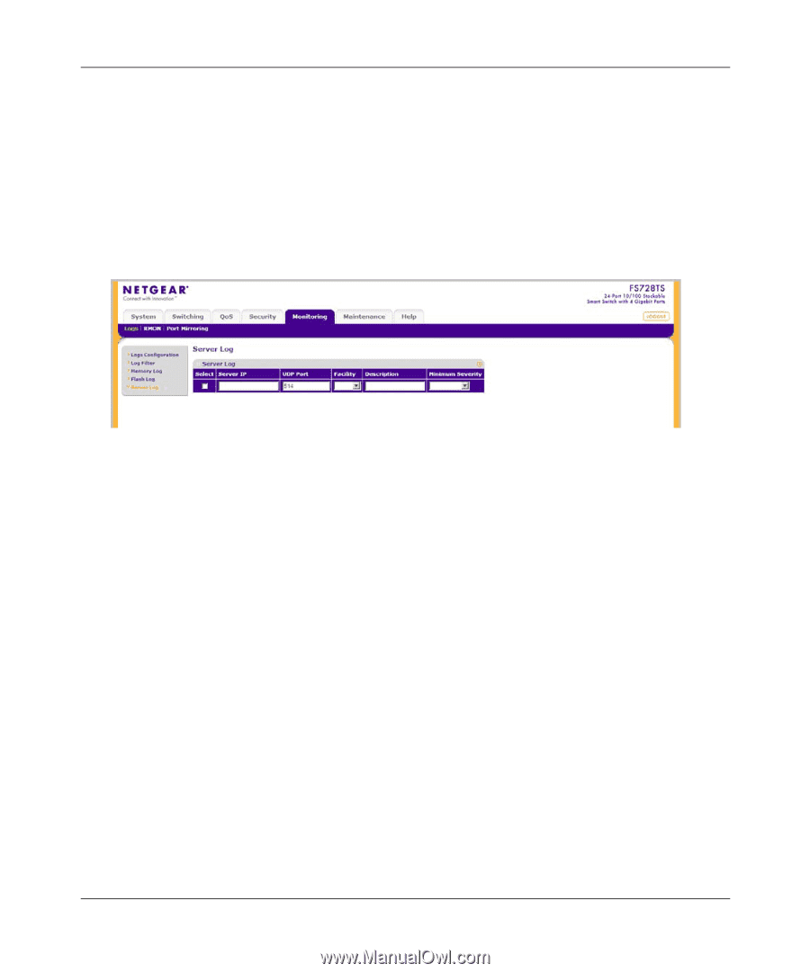
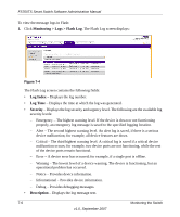
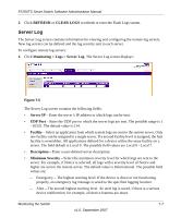
FS700TS Smart Switch Software Administration Manual 2. Click REFRESH or CLEAR LOGS to refresh or reset the Flash Logs screen. Server Log The Server Log screen contains information for viewing and configuring the remote log servers. New log servers can be defined and the log severity sent to each server. To configure remote log servers: 1. Click Monitoring > Logs > Server Log. The Server Log screen displays: Figure 7-5 The Server Log screen contains the following fields: • Server IP - Enter the server's IP address to which logs can be sent. • UDP Port - Enter the UDP port to which the server logs are sent. The possible range is 1 - 65535. The default value is 514. • Facility - Select an application from which system logs are sent to the remote server. Only one facility can be assigned to a single server. If a second facility level is assigned, the first facility is overridden. All applications defined for a device utilize the same facility on a server. The field default is Local 0. The possible field values are Local 0 - Local 7. • Description - Enter a user-defined server description. • Minimum Severity - Select the minimum severity level for which logs are sent to the server. For example, if Notice is selected, all logs with a severity level of Notice and higher are sent to the remote server. The default value is Informational. The possible field values are: - Emergency - The highest warning level. If the device is down or not functioning properly, an emergency log message is saved to the specified logging location. - Alert - The second highest warning level. An alert log is saved, if there is a serious device malfunction; for example, all device features are down. Monitoring the Switch 7-7 v1.0, September 2007
-
 1
1 -
2
-
3
-
4
-
5
-
6
-
7
-
8
-
9
-
10
-
11
-
12
-
13
-
14
-
15
-
16
-
17
-
18
-
19
-
20
-
21
-
22
-
23
-
24
-
25
-
26
-
27
-
28
-
29
-
30
-
31
-
32
-
33
-
34
-
35
-
36
-
37
-
38
-
39
-
40
-
41
-
42
-
43
-
44
-
45
-
46
-
47
-
48
-
49
-
50
-
51
-
52
-
53
-
54
-
55
-
56
-
57
-
58
-
59
-
60
-
61
-
62
-
63
-
64
-
65
-
66
-
67
-
68
-
69
-
70
-
71
-
72
-
73
-
74
-
75
-
76
-
77
-
78
-
79
-
80
-
81
-
82
-
83
-
84
-
85
-
86
-
87
-
88
-
89
-
90
-
91
-
92
-
93
-
94
-
95
-
96
-
97
-
98
-
99
-
100
-
101
-
102
-
103
-
104
-
105
-
106
-
107
-
108
-
109
-
110
-
111
-
112
-
113
-
114
-
115
-
116
-
117
-
118
-
119
-
120
-
121
-
122
-
123
-
124
-
125
-
126
-
127
-
128
-
129
-
130
-
131
-
132
-
133
-
134
-
135
-
136
-
137
-
138
-
139
-
140
-
141
-
142
-
143
-
144
-
145
-
146
-
147
-
148
-
149
-
150
-
151
-
 152
152 -
 153
153 -
 154
154 -
 155
155 -
 156
156 -
 157
157 -
 158
158 -
 159
159 -
 160
160 -
 161
161 -
 162
162 -
163
-
164
-
165
-
166
-
167
-
168
-
169
-
170
-
171
-
172
-
173
-
174
-
175
-
176
-
177
-
178
-
179
-
180
-
181
-
182
-
183
-
184
-
185
-
186
-
187
-
188
-
189
-
190
 |
 |