Netgear FS752TPS FS752TS Setup Manual - Page 170
Advanced > Alarms, Monitoring > RMON
 |
View all Netgear FS752TPS manuals
Add to My Manuals
Save this manual to your list of manuals |
Page 170 highlights
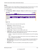
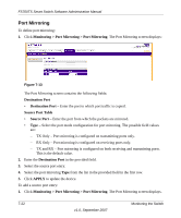
FS700TS Smart Switch Software Administration Manual • Falling Threshold - Enter the falling counter value that triggers the falling threshold alarm. The falling threshold is graphically presented on top of the graph bars. Each monitored variable is designated a color. • Falling Event - Enter the event number by which falling alarms are reported. • Startup Alarm - Select the trigger that activates the alarm generation. Rising is defined by crossing the threshold from a low-value threshold to a higher-value threshold. The possible field values are: - Rising Alarm - The alarm is triggered by the rising counter crossing the rising threshold value. - Falling Alarm - The alarm is triggered by the falling counter crossing the falling threshold value. - Rising and Falling - The alarm is triggered by either the rising counter crossing the rising threshold value or the falling counter crossing the falling threshold value. • Interval - Enter the alarm interval time in seconds. • Owner - Enter the device or user that defined the alarm. 2. Select the alarm entry. 3. Select the Counter Name from the list of MIB variable values in the provided field in the first row. 4. Enter the Interface in the provided field in the first row. 5. Select the Sample Type from the list in the provided field in the first row. 6. Select the Startup Alarm from the list in the provided field in the first row. 7. If you selected Rising Alarm or Rising and Falling as the Startup Alarm, enter the Rising Threshold and select the Rising Event number in the provided fields in the first row. 8. If you selected Falling Alarm or Rising and Falling as the Startup Alarm, enter the Falling Threshold and select the Falling Event number in the provided fields in the first row. 9. Enter the Interval and Owner in the provided fields in the first row. 10. Click APPLY to update the device. To add an alarm entry: 1. Click Monitoring > RMON > Advanced > Alarms. The RMON Alarms screen displays. 7-20 v1.0, September 2007 Monitoring the Switch
-
 1
1 -
2
-
3
-
4
-
5
-
6
-
7
-
8
-
9
-
10
-
11
-
12
-
13
-
14
-
15
-
16
-
17
-
18
-
19
-
20
-
21
-
22
-
23
-
24
-
25
-
26
-
27
-
28
-
29
-
30
-
31
-
32
-
33
-
34
-
35
-
36
-
37
-
38
-
39
-
40
-
41
-
42
-
43
-
44
-
45
-
46
-
47
-
48
-
49
-
50
-
51
-
52
-
53
-
54
-
55
-
56
-
57
-
58
-
59
-
60
-
61
-
62
-
63
-
64
-
65
-
66
-
67
-
68
-
69
-
70
-
71
-
72
-
73
-
74
-
75
-
76
-
77
-
78
-
79
-
80
-
81
-
82
-
83
-
84
-
85
-
86
-
87
-
88
-
89
-
90
-
91
-
92
-
93
-
94
-
95
-
96
-
97
-
98
-
99
-
100
-
101
-
102
-
103
-
104
-
105
-
106
-
107
-
108
-
109
-
110
-
111
-
112
-
113
-
114
-
115
-
116
-
117
-
118
-
119
-
120
-
121
-
122
-
123
-
124
-
125
-
126
-
127
-
128
-
129
-
130
-
131
-
132
-
133
-
134
-
135
-
136
-
137
-
138
-
139
-
140
-
141
-
142
-
143
-
144
-
145
-
146
-
147
-
148
-
149
-
150
-
151
-
152
-
153
-
154
-
155
-
156
-
157
-
158
-
159
-
160
-
161
-
162
-
163
-
164
-
 165
165 -
 166
166 -
 167
167 -
 168
168 -
 169
169 -
 170
170 -
 171
171 -
 172
172 -
 173
173 -
 174
174 -
 175
175 -
176
-
177
-
178
-
179
-
180
-
181
-
182
-
183
-
184
-
185
-
186
-
187
-
188
-
189
-
190
 |
 |