HP StorageWorks MSA 2/8 HP StorageWorks Fabric OS Procedures V3.1.x/4.1.x User - Page 18
Configuring a Logical Switch IP Address for the Core Switch 2/64, Example, Enter
 |
View all HP StorageWorks MSA 2/8 manuals
Add to My Manuals
Save this manual to your list of manuals |
Page 18 highlights
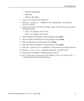
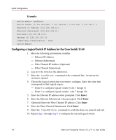
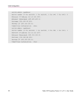
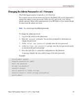
Initial Configuration Example: switch:admin> ipaddrset Switch number [0 for switch0, 1 for switch1, 2 for CP0, 3 for CP1]: 2 Ethernet IP Address [192.168.186.61]: Ethernet Subnetmask [255.255.255.0]: Hostname [192.168.68.193]: Gateway IP [255.255.255.0]: Committing configuration...Done. switch:admin> Configuring a Logical Switch IP Address for the Core Switch 2/64 1. Have the following information available: - Ethernet IP Address - Ethernet Subnetmask - Fibre Channel IP Address (Optional) - Fibre Channel Subnetmask 2. Log in to the switch as the admin user. 3. Enter the ipaddrset command at the command line. An interactive session is opened. 4. Choose the logical switch that you want to configure. Enter the value that corresponds to that logical region: - Enter 0 to configure logical switch 0 (slot 1 though 4) - Enter 1 to configure logical switch 1 (slot 7 though 10) 5. Enter the Ethernet IP address when prompted. Click Enter 6. Enter the Ethernet Subnetmask when prompted. Click Enter 7. (Optional) Enter the Fibre Channel IP address. Click Enter 8. Enter the Fibre Channel Subnetmask. Click Enter 9. Enter the ippaddrshow command to verify the data you entered, and exit. 10. Repeat step 1 through step 9 to configure the second logical switch. 18 Fabric OS Procedures Version 3.1.x/4.1.x User Guide
-
 1
1 -
2
-
3
-
4
-
5
-
6
-
7
-
8
-
9
-
10
-
11
-
12
-
 13
13 -
 14
14 -
 15
15 -
 16
16 -
 17
17 -
 18
18 -
 19
19 -
 20
20 -
 21
21 -
 22
22 -
 23
23 -
24
-
25
-
26
-
27
-
28
-
29
-
30
-
31
-
32
-
33
-
34
-
35
-
36
-
37
-
38
-
39
-
40
-
41
-
42
-
43
-
44
-
45
-
46
-
47
-
48
-
49
-
50
-
51
-
52
-
53
-
54
-
55
-
56
-
57
-
58
-
59
-
60
-
61
-
62
-
63
-
64
-
65
-
66
-
67
-
68
-
69
-
70
-
71
-
72
-
73
-
74
-
75
-
76
-
77
-
78
-
79
-
80
-
81
-
82
-
83
-
84
-
85
-
86
-
87
-
88
-
89
-
90
-
91
-
92
-
93
-
94
-
95
-
96
-
97
-
98
-
99
-
100
-
101
-
102
-
103
-
104
-
105
-
106
-
107
-
108
-
109
-
110
-
111
-
112
-
113
-
114
-
115
-
116
-
117
-
118
-
119
-
120
-
121
-
122
-
123
-
124
-
125
-
126
-
127
-
128
-
129
-
130
-
131
-
132
-
133
-
134
-
135
-
136
-
137
-
138
-
139
-
140
-
141
-
142
-
143
-
144
-
145
-
146
-
147
-
148
-
149
-
150
-
151
-
152
-
153
-
154
-
155
-
156
-
157
-
158
-
159
-
160
-
161
-
162
-
163
-
164
-
165
-
166
-
167
-
168
-
169
-
170
-
171
-
172
-
173
-
174
-
175
-
176
-
177
-
178
-
179
-
180
-
181
-
182
-
183
-
184
-
185
-
186
-
187
-
188
-
189
-
190
-
191
-
192
-
193
-
194
-
195
-
196
-
197
-
198
-
199
-
200
-
201
-
202
-
203
-
204
-
205
-
206
-
207
-
208
-
209
-
210
-
211
-
212
-
213
-
214
-
215
-
216
-
217
-
218
-
219
-
220
-
221
-
222
-
223
-
224
-
225
-
226
-
227
-
228
-
229
-
230
-
231
-
232
-
233
-
234
-
235
-
236
-
237
-
238
-
239
-
240
-
241
-
242
-
243
-
244
-
245
-
246
-
247
-
248
-
249
-
250
-
251
-
252
-
253
-
254
-
255
-
256
-
257
-
258
-
259
-
260
-
261
-
262
-
263
-
264
-
265
-
266
-
267
-
268
-
269
-
270
 |
 |