Brother International PR-620 Users Manual - English - Page 185
Optional Accessories
 |
View all Brother International PR-620 manuals
Add to My Manuals
Save this manual to your list of manuals |
Page 185 highlights
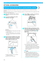
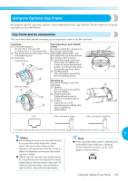
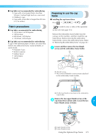
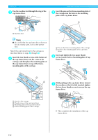
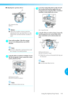
APPENDIX OPTIONAL ACCESSORIES Attaching an optional embroidery frame for industrial embroidery machines Prepare the embroidery frame holder in order to attach the embroidery frame for industrial embroidery machines. When the embroidery frame for industrial embroidery machines is attached, both the left and right arms of the embroidery frame holder moves. Remove the embroidery frame. (Refer to 1 page 46.) Using a Phillips screwdriver, loosen the two 4 screws, and then remove them. Loosen the two thumb screws on the 2 embroidery frame holder. 2 1 1 Left arm 2 Thumb screws X The left arm of the embroidery frame holder can be moved. • Only loosen the thumb screws a maximum of 2 turns counterclockwise. Do not remove the screw. Move the left arm to align the screw on the 3 right side with the mark for the embroidery frame for industrial embroidery machines, and then tighten the thumb screws. Remove the right arm, align the pins on the 5 embroidery frame holder with the holes in the arm, as shown in the illustration, and then insert the screws removed in step 4 and tighten them. 1 Mark for embroidery frame for industrial embroidery machines 2 Align the screw with the mark. 168 X The embroidery frame holder is ready for the embroidery frame to be attached. Attach the embroidery frame for industrial embroidery machines in the same way that enclosed embroidery frames are attached. (Refer to page 30.) Note ● When using embroidery frames for industrial embroidery machines, THE MACHINE DOES NOT RECOGNIZE THE SEWING AREA OF THE FRAME. Be sure to use the trial sewing function to check that the pattern fits within the sewing area.
-
 1
1 -
2
-
3
-
4
-
5
-
6
-
7
-
8
-
9
-
10
-
11
-
12
-
13
-
14
-
15
-
16
-
17
-
18
-
19
-
20
-
21
-
22
-
23
-
24
-
25
-
26
-
27
-
28
-
29
-
30
-
31
-
32
-
33
-
34
-
35
-
36
-
37
-
38
-
39
-
40
-
41
-
42
-
43
-
44
-
45
-
46
-
47
-
48
-
49
-
50
-
51
-
52
-
53
-
54
-
55
-
56
-
57
-
58
-
59
-
60
-
61
-
62
-
63
-
64
-
65
-
66
-
67
-
68
-
69
-
70
-
71
-
72
-
73
-
74
-
75
-
76
-
77
-
78
-
79
-
80
-
81
-
82
-
83
-
84
-
85
-
86
-
87
-
88
-
89
-
90
-
91
-
92
-
93
-
94
-
95
-
96
-
97
-
98
-
99
-
100
-
101
-
102
-
103
-
104
-
105
-
106
-
107
-
108
-
109
-
110
-
111
-
112
-
113
-
114
-
115
-
116
-
117
-
118
-
119
-
120
-
121
-
122
-
123
-
124
-
125
-
126
-
127
-
128
-
129
-
130
-
131
-
132
-
133
-
134
-
135
-
136
-
137
-
138
-
139
-
140
-
141
-
142
-
143
-
144
-
145
-
146
-
147
-
148
-
149
-
150
-
151
-
152
-
153
-
154
-
155
-
156
-
157
-
158
-
159
-
160
-
161
-
162
-
163
-
164
-
165
-
166
-
167
-
168
-
169
-
170
-
171
-
172
-
173
-
174
-
175
-
176
-
177
-
178
-
179
-
 180
180 -
 181
181 -
 182
182 -
 183
183 -
 184
184 -
 185
185 -
 186
186 -
 187
187 -
 188
188 -
 189
189 -
 190
190 -
191
-
192
-
193
-
194
-
195
-
196
-
197
-
198
-
199
-
200
-
201
-
202
-
203
-
204
-
205
-
206
-
207
-
208
-
209
-
210
-
211
-
212
-
213
-
214
-
215
-
216
-
217
-
218
-
219
-
220
-
221
-
222
-
223
-
224
-
225
-
226
-
227
-
228
-
229
-
230
-
231
-
232
-
233
-
234
-
235
-
236
-
237
 |
 |