Brother International PR-620 Users Manual - English - Page 201
Removing the cap frame
 |
View all Brother International PR-620 manuals
Add to My Manuals
Save this manual to your list of manuals |
Page 201 highlights
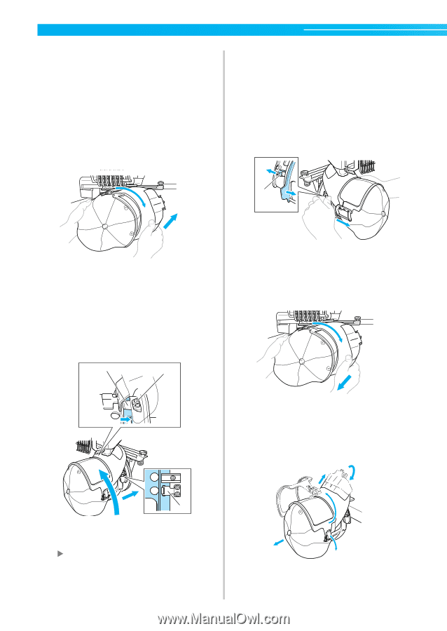
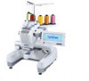
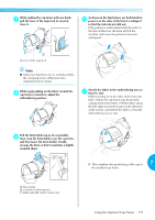
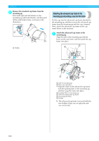
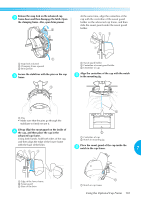
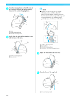
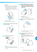
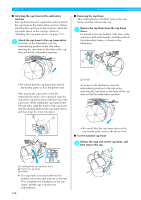
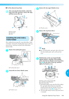
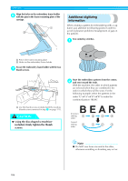
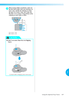
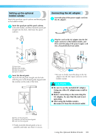
APPENDIX ■ Attaching the cap frame to the embroidery machine The cap frame driver is required in order to attach the cap frame to the embroidery machine. Before attaching the cap frame to the machine, attach the cap frame driver to the carriage. (Refer to "Installing the cap frame driver" on page 171.) Attach the cap frame to the cap frame driver. 1 As shown in the illustration, turn the embroidering position to the side when inserting the cap frame so the brim of the cap does not hit the embroidery machine. ■ Removing the cap frame After embroidering is finished, remove the cap frame, and then remove the cap. Remove the cap frame from the cap frame 1 driver. Press both of the two holders at the base of the cap frame with both thumbs, and then pull off the embroidery frame, as shown in the illustration. 1 • Be careful that the cap frame does not hit any nearby parts, such as the presser foot. After turning the cap frame so that the embroidering surface faces upward, align the ring of the cap frame driver with the ring of the cap frame. While sliding the cap frame to the left and right, align the notch in the cap frame with the guiding plate on the cap frame driver, and then snap the frame into place. 2 1 1 Holder As shown in the illustration, turn the embroidering position to the side when removing the cap frame so the brim of the cap does not hit the embroidery machine. • Be careful that the cap frame does not hit any nearby parts, such as the presser foot. ■ For the standard cap frame Release the snap lock on the cap frame, and 2 then remove the cap. 3 2 1 Guiding Plate on cap frame driver 2 Notch on cap frame 3 Holder 1 X The cap frame is secured with the two holders one on the right and one on the left. This completes the installation of the cap frame, and the cap is ready to be embroidered. 184
-
 1
1 -
2
-
3
-
4
-
5
-
6
-
7
-
8
-
9
-
10
-
11
-
12
-
13
-
14
-
15
-
16
-
17
-
18
-
19
-
20
-
21
-
22
-
23
-
24
-
25
-
26
-
27
-
28
-
29
-
30
-
31
-
32
-
33
-
34
-
35
-
36
-
37
-
38
-
39
-
40
-
41
-
42
-
43
-
44
-
45
-
46
-
47
-
48
-
49
-
50
-
51
-
52
-
53
-
54
-
55
-
56
-
57
-
58
-
59
-
60
-
61
-
62
-
63
-
64
-
65
-
66
-
67
-
68
-
69
-
70
-
71
-
72
-
73
-
74
-
75
-
76
-
77
-
78
-
79
-
80
-
81
-
82
-
83
-
84
-
85
-
86
-
87
-
88
-
89
-
90
-
91
-
92
-
93
-
94
-
95
-
96
-
97
-
98
-
99
-
100
-
101
-
102
-
103
-
104
-
105
-
106
-
107
-
108
-
109
-
110
-
111
-
112
-
113
-
114
-
115
-
116
-
117
-
118
-
119
-
120
-
121
-
122
-
123
-
124
-
125
-
126
-
127
-
128
-
129
-
130
-
131
-
132
-
133
-
134
-
135
-
136
-
137
-
138
-
139
-
140
-
141
-
142
-
143
-
144
-
145
-
146
-
147
-
148
-
149
-
150
-
151
-
152
-
153
-
154
-
155
-
156
-
157
-
158
-
159
-
160
-
161
-
162
-
163
-
164
-
165
-
166
-
167
-
168
-
169
-
170
-
171
-
172
-
173
-
174
-
175
-
176
-
177
-
178
-
179
-
180
-
181
-
182
-
183
-
184
-
185
-
186
-
187
-
188
-
189
-
190
-
191
-
192
-
193
-
194
-
195
-
 196
196 -
 197
197 -
 198
198 -
 199
199 -
 200
200 -
 201
201 -
 202
202 -
 203
203 -
 204
204 -
 205
205 -
 206
206 -
207
-
208
-
209
-
210
-
211
-
212
-
213
-
214
-
215
-
216
-
217
-
218
-
219
-
220
-
221
-
222
-
223
-
224
-
225
-
226
-
227
-
228
-
229
-
230
-
231
-
232
-
233
-
234
-
235
-
236
-
237
 |
 |