Brother International PR-620 Users Manual - English - Page 193
Attaching the standard cap frame to the, mounting jig and putting a cap into the frame
 |
View all Brother International PR-620 manuals
Add to My Manuals
Save this manual to your list of manuals |
Page 193 highlights
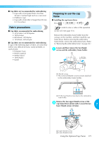
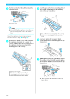
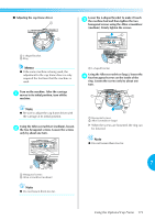
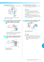
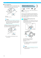
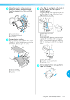
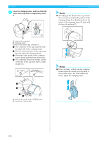
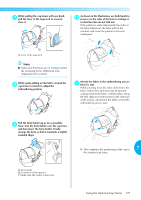
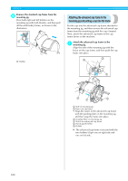
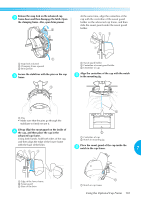
APPENDIX ■ For the standard type Using a Phillips screwdriver, turn the four screws (two on the left and two on the right) at the inside of the mounting jig one turn to loosen them. Attaching the standard cap frame to the mounting jig and putting a cap into the frame Press → → →→ in order to view a video of the operation on 2 1 the LCD (see page 151). 1 Screws 2 Phillips screwdriver Note ● Do not remove any of the four screws (two on the left and two on the right); otherwise, they may be lost. Only turn the screws to slightly loosen them. Pull the mounting jig toward you, and then use the Phillips screwdriver to tighten the four screws (two on the left and two on the right). Put the cap into the standard cap frame attached to the mounting jig, and then remove the standard cap frame from the mounting jig with the cap clamped. Next, attach the standard cap frame to the cap frame driver on the machine. Attach the standard cap frame to the 1 mounting jig. Align the notch in the standard cap frame with the guiding plate on the mounting jig, and then snap the frame into place. 1 2 3 X This completes the preparation of the mounting jig. 4 1 Guiding Plate on mounting jig 2 Notch on standard cap frame 3 Sweat guard holder 4 Holder X The standard cap frame is secured with the two holders (clips) one on right side and one on left side. Note ● Make sure that the mounting jig is set to the standard position. 176
-
 1
1 -
2
-
3
-
4
-
5
-
6
-
7
-
8
-
9
-
10
-
11
-
12
-
13
-
14
-
15
-
16
-
17
-
18
-
19
-
20
-
21
-
22
-
23
-
24
-
25
-
26
-
27
-
28
-
29
-
30
-
31
-
32
-
33
-
34
-
35
-
36
-
37
-
38
-
39
-
40
-
41
-
42
-
43
-
44
-
45
-
46
-
47
-
48
-
49
-
50
-
51
-
52
-
53
-
54
-
55
-
56
-
57
-
58
-
59
-
60
-
61
-
62
-
63
-
64
-
65
-
66
-
67
-
68
-
69
-
70
-
71
-
72
-
73
-
74
-
75
-
76
-
77
-
78
-
79
-
80
-
81
-
82
-
83
-
84
-
85
-
86
-
87
-
88
-
89
-
90
-
91
-
92
-
93
-
94
-
95
-
96
-
97
-
98
-
99
-
100
-
101
-
102
-
103
-
104
-
105
-
106
-
107
-
108
-
109
-
110
-
111
-
112
-
113
-
114
-
115
-
116
-
117
-
118
-
119
-
120
-
121
-
122
-
123
-
124
-
125
-
126
-
127
-
128
-
129
-
130
-
131
-
132
-
133
-
134
-
135
-
136
-
137
-
138
-
139
-
140
-
141
-
142
-
143
-
144
-
145
-
146
-
147
-
148
-
149
-
150
-
151
-
152
-
153
-
154
-
155
-
156
-
157
-
158
-
159
-
160
-
161
-
162
-
163
-
164
-
165
-
166
-
167
-
168
-
169
-
170
-
171
-
172
-
173
-
174
-
175
-
176
-
177
-
178
-
179
-
180
-
181
-
182
-
183
-
184
-
185
-
186
-
187
-
 188
188 -
 189
189 -
 190
190 -
 191
191 -
 192
192 -
 193
193 -
 194
194 -
 195
195 -
 196
196 -
 197
197 -
 198
198 -
199
-
200
-
201
-
202
-
203
-
204
-
205
-
206
-
207
-
208
-
209
-
210
-
211
-
212
-
213
-
214
-
215
-
216
-
217
-
218
-
219
-
220
-
221
-
222
-
223
-
224
-
225
-
226
-
227
-
228
-
229
-
230
-
231
-
232
-
233
-
234
-
235
-
236
-
237
 |
 |
