Brother International PR-620 Users Manual - English - Page 192
mounting surface by tightening the thumb
 |
View all Brother International PR-620 manuals
Add to My Manuals
Save this manual to your list of manuals |
Page 192 highlights
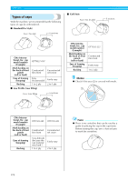
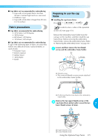
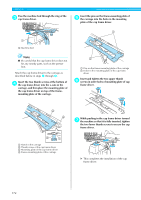
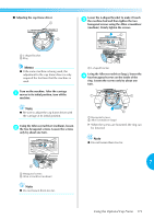
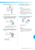
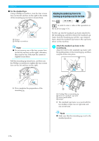
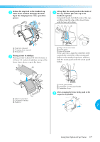
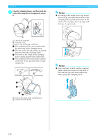
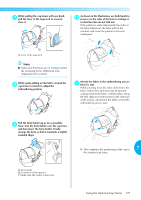
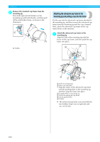
Tighten the two screws. 2 • Make sure that the stopper is firmly secured. Check that there is no looseness. 5 If there is looseness, mount the mounting jig onto the mounting surface again. Attach the mounting jig to a stable mounting surface, such as a desk. Loosen the thumb screw for the mounting jig 3 to open the mounting bracket so that it is wider than the thickness of the mounting plate. Note ● Be sure that the mounting bracket is securely clamped onto the mounting surface and that the thumb screw is firmly tightened. ● Do not attach the mounting jig to an unstable surface (flexible, bent or warped). ● Be careful that the mounting jig does not fall when it is removed. Adjust the size of the mounting jig according 6 to the type of cap being embroidered. • The mounting bracket can be mounted onto a plate with a thickness from 9 mm (3/8 inch) to 38 mm (1-1/2 inches). Securely clamp the mounting bracket onto the 4 mounting surface by tightening the thumb screw. 1 2 3 1 Mounting bracket 2 Mounting surface 3 Tighten thumb screw 1 2 1 Low Profile (Low fitting) 2 Standard (Pro style) Note ● Either the standard type cap frame or the advanced type cap frame can be used in the standard position. Only the advanced cap frame can be used in the low profile position. 7 Using the Optional Cap Frame 175
-
 1
1 -
2
-
3
-
4
-
5
-
6
-
7
-
8
-
9
-
10
-
11
-
12
-
13
-
14
-
15
-
16
-
17
-
18
-
19
-
20
-
21
-
22
-
23
-
24
-
25
-
26
-
27
-
28
-
29
-
30
-
31
-
32
-
33
-
34
-
35
-
36
-
37
-
38
-
39
-
40
-
41
-
42
-
43
-
44
-
45
-
46
-
47
-
48
-
49
-
50
-
51
-
52
-
53
-
54
-
55
-
56
-
57
-
58
-
59
-
60
-
61
-
62
-
63
-
64
-
65
-
66
-
67
-
68
-
69
-
70
-
71
-
72
-
73
-
74
-
75
-
76
-
77
-
78
-
79
-
80
-
81
-
82
-
83
-
84
-
85
-
86
-
87
-
88
-
89
-
90
-
91
-
92
-
93
-
94
-
95
-
96
-
97
-
98
-
99
-
100
-
101
-
102
-
103
-
104
-
105
-
106
-
107
-
108
-
109
-
110
-
111
-
112
-
113
-
114
-
115
-
116
-
117
-
118
-
119
-
120
-
121
-
122
-
123
-
124
-
125
-
126
-
127
-
128
-
129
-
130
-
131
-
132
-
133
-
134
-
135
-
136
-
137
-
138
-
139
-
140
-
141
-
142
-
143
-
144
-
145
-
146
-
147
-
148
-
149
-
150
-
151
-
152
-
153
-
154
-
155
-
156
-
157
-
158
-
159
-
160
-
161
-
162
-
163
-
164
-
165
-
166
-
167
-
168
-
169
-
170
-
171
-
172
-
173
-
174
-
175
-
176
-
177
-
178
-
179
-
180
-
181
-
182
-
183
-
184
-
185
-
186
-
 187
187 -
 188
188 -
 189
189 -
 190
190 -
 191
191 -
 192
192 -
 193
193 -
 194
194 -
 195
195 -
 196
196 -
 197
197 -
198
-
199
-
200
-
201
-
202
-
203
-
204
-
205
-
206
-
207
-
208
-
209
-
210
-
211
-
212
-
213
-
214
-
215
-
216
-
217
-
218
-
219
-
220
-
221
-
222
-
223
-
224
-
225
-
226
-
227
-
228
-
229
-
230
-
231
-
232
-
233
-
234
-
235
-
236
-
237
 |
 |
