HP Xw5000 hp workstation xw5000 Technical Reference (309233-001 10/02)
HP Xw5000 - Workstation - 512 MB RAM Manual
 |
UPC - 613326803318
View all HP Xw5000 manuals
Add to My Manuals
Save this manual to your list of manuals |
HP Xw5000 manual content summary:
- HP Xw5000 | hp workstation xw5000 Technical Reference (309233-001 10/02) - Page 1
Technical Reference Guide HP Workstation xw5000 Manufacturing Part Number : 309233-001 © Copyright 2003 Hewlett-Packard Company. - HP Xw5000 | hp workstation xw5000 Technical Reference (309233-001 10/02) - Page 2
for a particular purpose. Hewlett-Packard shall not be liable for errors contained herein or for incidental or consequential damages in connection with trademark of Matrox Electronic Systems Ltd. Microsoft®, Windows®, MS-DOS®, Windows NT® and Windows 2000® are registered trademarks of the Microsoft - HP Xw5000 | hp workstation xw5000 Technical Reference (309233-001 10/02) - Page 3
when extensive changes are made. Manual updates may be issued between editions to correct errors or document product changes. To ensure that you receive the updated or new editions, you should subscribe to the appropriate product support service. See your HP Sales Representative for details. First - HP Xw5000 | hp workstation xw5000 Technical Reference (309233-001 10/02) - Page 4
- HP Xw5000 | hp workstation xw5000 Technical Reference (309233-001 10/02) - Page 5
Cooling 18 System Fans and Airflow 19 Resetting the Power Supply 20 Environmental Specifications 21 Where to Get Help 22 Contacting HP Customer Care 22 Information You Need 22 Online Support, Drivers and Documentation 23 2. Installing or Replacing Parts and Accessories Overview 26 Internal - HP Xw5000 | hp workstation xw5000 Technical Reference (309233-001 10/02) - Page 6
Configuration and Monitoring Configuring your Workstation with the HP Setup Program 78 Starting the HP Setup Program 78 Main Menu 79 Advanced Menu 79 Security Menu 80 Boot Menu 82 Power Menu 82 BIOS Features and Specifications 83 BIOS Version 84 Updating the System BIOS 84 Restoring BIOS - HP Xw5000 | hp workstation xw5000 Technical Reference (309233-001 10/02) - Page 7
Mouse Doesn't Work 92 Audio Doesn't Work 93 Optical Drive Problems 94 Hard Disk Drive Problems 96 Understanding the LED messages 97 Power LED is Flashing or Red 97 Hard Disk Drive Activity LED Doesn't Work 97 Understanding Power-on-Self-Test messages 98 Troubleshooting with the e-buzzer 100 - HP Xw5000 | hp workstation xw5000 Technical Reference (309233-001 10/02) - Page 8
Contents - HP Xw5000 | hp workstation xw5000 Technical Reference (309233-001 10/02) - Page 9
open the laser module. The laser module should be serviced by service personnel only. Do not attempt to make any adjustment to model, or if you have installed a sound card in your system, always turn the volume down before network. Always replace the cover before switching the workstation on again. - HP Xw5000 | hp workstation xw5000 Technical Reference (309233-001 10/02) - Page 10
you bought them, to the dealer from whom you purchased your workstation, or to HP so that they can either be recycled or disposed of in the communications board without first removing the connection to the telephone network. Static Electricity Static electricity can damage electronic components. Turn - HP Xw5000 | hp workstation xw5000 Technical Reference (309233-001 10/02) - Page 11
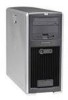
1 Product Information This chapter: • Introduces the workstation internal and external components • Lists the system specifications and characteristic data • Provides a summary of available documentation and support - HP Xw5000 | hp workstation xw5000 Technical Reference (309233-001 10/02) - Page 12
complete list of components and part numbers, see the hp workstation xw5000 Illustrated Parts Map provided with your system. For updated information about available graphics cards, drives and accessories, go to: Workstation Physical Characteristics Weight Dimensions Tower Rack Mount (with cosmetic - HP Xw5000 | hp workstation xw5000 Technical Reference (309233-001 10/02) - Page 13
hp workstation xw5000 Getting Started Guide and your OS documentation for more information.) - Flashing yellow, flashing red, or solid red: System error. • Hard Disk Activity LED - flickers when your hard disk is being accessed. Activated during Power-on Self Test (POST) and during hard disk drive - HP Xw5000 | hp workstation xw5000 Technical Reference (309233-001 10/02) - Page 14
Figure 1-2 Rear Panel Features Rear View of Workstation - HP Xw5000 | hp workstation xw5000 Technical Reference (309233-001 10/02) - Page 15
Figure 1-3 Internal Features Side View of Workstation - HP Xw5000 | hp workstation xw5000 Technical Reference (309233-001 10/02) - Page 16
1-2 Power Supply and Cooling The workstation power supply has five outputs: • +3.3V - PCI, AGP, Granite Bay MCH, ICH4, Audio, SCSI, on-board logic and input for on-board voltage regulators • +5V - disk drives, PCI, AGP, and on-board logic • +12V - fans, PCI, AGP, disk drives, and input to on-board - HP Xw5000 | hp workstation xw5000 Technical Reference (309233-001 10/02) - Page 17
Table 1-3 Power Supply Input Requirements xw5000 Power Supply Input Requirements Input voltage range(s) 240VAC 35 A @ 110 V 76 A @ 240V 5.5 Arms @ 90VAC For power cord and plug specifications (depending on country, voltage, and current), see: Standard cord length is approximately 2m (6 ft.). - HP Xw5000 | hp workstation xw5000 Technical Reference (309233-001 10/02) - Page 18
configuration: • One processor • 1 GB memory • Two hard disk drives • DVD ROM drive • Floppy drive • Graphics card when the workstation is off, either unplug the workstation from the power AGP a. AGP Card Specification: 8x AGP Pro50. PCI Specification: PCI 2.2. b. If an AGP Pro 50 card is installed, - HP Xw5000 | hp workstation xw5000 Technical Reference (309233-001 10/02) - Page 19
Figure 1-4 System Fans and Airflow The xw5000 workstation includes the following fans: • One system fan • One processor heatsink fan Fans - HP Xw5000 | hp workstation xw5000 Technical Reference (309233-001 10/02) - Page 20
supply unit: 1. Disconnect the power cord. 2. Determine what caused the overload, and fix the problem. 3. Reconnect the power cord, and reboot the workstation. When you power down the workstation through the operating system, power consumption falls below the low power consumption, but doesn't reach - HP Xw5000 | hp workstation xw5000 Technical Reference (309233-001 10/02) - Page 21
Environmental Specifications Environmental Specifications Storage humidity 90% (relative, non-condensing) Operating humidity 15% to 80% (relative, non-condensing) at 35° C (95° F) Storage temperature -40° C (-40° F) to 70° C (158° F) Operating - HP Xw5000 | hp workstation xw5000 Technical Reference (309233-001 10/02) - Page 22
the problem. 4. Get the e-buzzer error and try to solve the problem according to the solutions suggested in the table. 5. Use the diagnostic software on your system to generate a support ticket. See the hp workstation xw5000 Getting Started Guide provided with your system for detailed instructions. - HP Xw5000 | hp workstation xw5000 Technical Reference (309233-001 10/02) - Page 23
Go to to obtain online support information, and: • BIOS updates (including the upgrade utility and instructions) • The latest drivers and software utilities • Additional documentation - Installation Poste: basic information on setting up your new workstation - Getting Started Guide (this document - HP Xw5000 | hp workstation xw5000 Technical Reference (309233-001 10/02) - Page 24
- HP Xw5000 | hp workstation xw5000 Technical Reference (309233-001 10/02) - Page 25
2 Installing or Replacing Parts and Accessories - HP Xw5000 | hp workstation xw5000 Technical Reference (309233-001 10/02) - Page 26
the HP Workstation xw5000 Illustrated Parts Map. For updated information about available graphics cards, drives, and accessories, go to: Check your configuration every time you install, remove, or upgrade an accessory. For instructions on how to check your configuration using the HP Setup program - HP Xw5000 | hp workstation xw5000 Technical Reference (309233-001 10/02) - Page 27
Figure 2-1 Internal Components Figure 2-1 shows the system board layout. xw5000 System Board - HP Xw5000 | hp workstation xw5000 Technical Reference (309233-001 10/02) - Page 28
in this chapter, you must: • power off the workstation, and • unplug the workstation power cord from the AC power outlet. To maintain FCC , use either a: • Flat blade screwdriver, or • T-15 Torx driver Follow Electrostatic Discharge (ESD) Precautions To prevent damage to the system, observe - HP Xw5000 | hp workstation xw5000 Technical Reference (309233-001 10/02) - Page 29
and unplug the power cord from the outlet or Power Protection Device before you remove the covers. Always replace the cover(s) before you turn on the workstation. Removing the Side Cover To remove the side cover: 1. Shut down the workstation and turn off the display. Disconnect all power cables and - HP Xw5000 | hp workstation xw5000 Technical Reference (309233-001 10/02) - Page 30
Figure 2-3 Removing the Front Bezel Remove the front bezel only when you add or remove devices in the front drive bays or replace front-panel connectors. To remove the front bezel: 1. Remove the side cover. 2. Gently lift the three plastic tabs on the left side - HP Xw5000 | hp workstation xw5000 Technical Reference (309233-001 10/02) - Page 31
. Bezel Alignment b. Rotate the bezel into position and verify that the plastic tabs on the left side of the bezel click into position on the workstation chassis. The bezel should be flush against the - HP Xw5000 | hp workstation xw5000 Technical Reference (309233-001 10/02) - Page 32
Figure 2-5 3. Lower the cover onto the chassis (aligning the guide rail on the bottom inside edge of the cover with the bottom edge of the workstation chassis). 4. Close the cover. Aligning and Closing the Cover 5. If desired, lock the cover using the key provided. - HP Xw5000 | hp workstation xw5000 Technical Reference (309233-001 10/02) - Page 33
more than one DIMM is installed Use only HP DIMMs specifically designed for your workstation model. For a complete list of supported memory modules, see the Illustrated Parts Map or go to . Figure 2-6 Removing Memory Modules To remove a memory module: 1. Turn off the system, disconnect all cables - HP Xw5000 | hp workstation xw5000 Technical Reference (309233-001 10/02) - Page 34
3. If the removed memory is functional, store it in a static-free container for future use. 4. Replace the system covers, reconnect all cables, and turn on the system. - HP Xw5000 | hp workstation xw5000 Technical Reference (309233-001 10/02) - Page 35
disconnect all cables, and remove the system cover (page 29). Place the workstation on its side with the system board facing up. To ensure that memory modules are not damaged during removal or installation, power off the workstation and unplug the power cord from the AC power outlet. Wait until the - HP Xw5000 | hp workstation xw5000 Technical Reference (309233-001 10/02) - Page 36
direction. Be careful to align the notch on the module with the key on the connector. Memory Modules Installed in Pair 1 3. When the module is correctly seated, the retainer clips return all cables, and turn on the system. 5. Start the workstation. Press when prompted to check the verify the new - HP Xw5000 | hp workstation xw5000 Technical Reference (309233-001 10/02) - Page 37
cables. 2. Remove the side cover (page 29). 3. Remove any cables connected to the card on the rear panel. 4. Place the workstation on its side with the system board facing up. 5. Remove the AGP Card Support Assembly, if applicable: a. Squeeze the two sides of the retainer to release the locking - HP Xw5000 | hp workstation xw5000 Technical Reference (309233-001 10/02) - Page 38
Figure 2-10 6. Open the PCI retainer by pressing down on the two green clips at the ends of the retainer and rotating the retainer towards the back of the system. PCI Retainer Clips (inside of case) Figure 2-11 If it is difficult to disengage the green clips, press the outside of the clips from - HP Xw5000 | hp workstation xw5000 Technical Reference (309233-001 10/02) - Page 39
For full-length cards, disengage the front of the card from the card guide by removing the screw and releasing the card guide locking clip. Figure 2-12 Full-length Card Guide 8. Grasp the bulkhead end of the card and its opposite edge and lift the card out of the slot. Store the card in a static bag - HP Xw5000 | hp workstation xw5000 Technical Reference (309233-001 10/02) - Page 40
with your card and your OS manual for information on installing new drivers and configuring video settings. Refer to the graphics documentation provided at your graphics card kit for more information. or with Booting from a PCI Device To boot from a PCI device, such as a Network card, enable - HP Xw5000 | hp workstation xw5000 Technical Reference (309233-001 10/02) - Page 41
SCSI controller card (see "Installing a Graphics or Accessory Card" on page 39), or • One or two IDE drives using the integrated IDE controller Back up your files before removing or installing a hard disk drive. Removing a Hard Drive To remove a hard drive: 1. Shut down the workstation and turn - HP Xw5000 | hp workstation xw5000 Technical Reference (309233-001 10/02) - Page 42
release clips on the sides of the drive, and squeeze inward. Pull gently just enough to release the drive rail latches. Figure 2-15 Hard Drive Rails 6. Grasp the hard drive with your hand and pull out. The drive rails are not screwed on to the drive. Do not hold the drive by the rails when it is not - HP Xw5000 | hp workstation xw5000 Technical Reference (309233-001 10/02) - Page 43
Figure 2-17 Installing a Hard Drive To install a hard drive: 1. If you are replacing a drive, remove the existing drive (page 41) in the slot you want to use. 2. Connect rails to the new drive: a. If the rails are stored in the drive bay, place your fingers on the colored release clips located on - HP Xw5000 | hp workstation xw5000 Technical Reference (309233-001 10/02) - Page 44
2-18 3. Insert the drive into the bay. Load the drives in the order shown in Figure 2-18 (IDE) orFigure 2-19 (SCSI): Hold onto the hard drive - NOT the rails - when handling the drive. a. For IDE drives, insert the first drive into bay 2 (second from bottom), and the second drive into bay 3 (third - HP Xw5000 | hp workstation xw5000 Technical Reference (309233-001 10/02) - Page 45
b. For SCSI drives, insert the drive into the next available bay, loading the drives in the order shown below. Press down gently until the drive snaps into place. Figure 2-19SCSI Drive Loading Order - HP Xw5000 | hp workstation xw5000 Technical Reference (309233-001 10/02) - Page 46
By First SCSI hard drive Optional additional SCSI hard drives Unused SCSI controller Unused 5. Replace the workstation cover (page 31) and reconnect all power cables and any LAN or telecommunications cables. 6. Start the workstation and check the to verify the new configuration. by pressing when - HP Xw5000 | hp workstation xw5000 Technical Reference (309233-001 10/02) - Page 47
Figure 2-20 Optical Drives The optical drives in the xw5000 workstation are IDE devices. Removing an Optical Drive To remove an optical drive: 1. Shut down the workstation and turn off the display. Disconnect all power cables and any LAN or telecommunications cables. 2. Remove the side cover and - HP Xw5000 | hp workstation xw5000 Technical Reference (309233-001 10/02) - Page 48
the drive before you can write to the device or play DVD movies. The CD-ROM driver is pre-loaded and is used by the CD-ROM, CD-RW, and DVD drives to read standard CD-ROM format media. Refer to the HP Workstation xw5000 Getting Started Guide provided with your system for installation instructions. - HP Xw5000 | hp workstation xw5000 Technical Reference (309233-001 10/02) - Page 49
Drive Removing a Floppy Drive To remove a floppy drive: 1. Shut down the workstation and turn off the display. Disconnect all power cables and any LAN or telecommunications cables. 2. Remove the side cover and front bezel (page 29). 3. Remove the power and data cables from the drive. Floppy Drive - HP Xw5000 | hp workstation xw5000 Technical Reference (309233-001 10/02) - Page 50
Figure 2-25 Installing a Floppy Drive To install a floppy drive: 1. Shut down the workstation and turn off the display. Disconnect all power cables and any LAN or telecommunications cables. 2. Remove the side cover and front bezel (page 29). 3. Remove the old floppy drive from the bay. 4. Insert - HP Xw5000 | hp workstation xw5000 Technical Reference (309233-001 10/02) - Page 51
power supply upgrades. This information is provided to help you replace a defective power supply unit. For your safety, only use a power supply provided by HP support services. Removing the Power Supply To remove the power supply: 1. Shut down the workstation and turn off the display. Disconnect all - HP Xw5000 | hp workstation xw5000 Technical Reference (309233-001 10/02) - Page 52
5. Remove the four screws located on the rear of the chassis that secure the power supply unit in position. Figure 2-27 Power Supply Mounting Screws Figure 2-28 6. Push the supply unit forward until it is clear of the mounting hooks and remove it from the chassis. Removing the Power Supply - HP Xw5000 | hp workstation xw5000 Technical Reference (309233-001 10/02) - Page 53
using the four screws you previously removed (Figure 2-27 on page 52). 4. Reconnect all internal power supply connectors (Figure 2-26 on page 51). 5. Return the workstation to its upright position. 6. Replace the cover (page 31). 7. Reconnect all the power and telecommunications cables. - HP Xw5000 | hp workstation xw5000 Technical Reference (309233-001 10/02) - Page 54
and turn off the display. Disconnect all power cables and any LAN or telecommunications cables. 2. Remove the side cover (page 29). 3. Place your workstation on its side with the system board facing up. 4. Disconnect the fan connector from the system board, noting where it was plugged in so you - HP Xw5000 | hp workstation xw5000 Technical Reference (309233-001 10/02) - Page 55
Figure 2-31 Installing a System Fan The workstation ships with one system fan. An optional front fan may be added after purchase. To install a second fan, follow the instructions provided with fan. To install the system fan: 1. Remove the old fan (page 54). 2. Ensure that all cables are clear of - HP Xw5000 | hp workstation xw5000 Technical Reference (309233-001 10/02) - Page 56
5. Connect the fan connector to the system board, making sure it is in correct connector. Figure 2-32 System Fan Connector 6. Replace the cover (page 31). Reconnect all the power and telecommunications cables. - HP Xw5000 | hp workstation xw5000 Technical Reference (309233-001 10/02) - Page 57
the display. Disconnect all power cables and any LAN or telecommunications cables. 2. Remove the side cover and front bezel (page 29). 3. Place the workstation on its side with the system board facing up. 4. Remove the control panel cable from the system board. Figure 2-33 Control Panel Connector - HP Xw5000 | hp workstation xw5000 Technical Reference (309233-001 10/02) - Page 58
place by two plastic tabs that are accessible through holes in the top and bottom of the intrusion switch bracket. Depress the tabs with a screw driver, and push the button down and out of the bracket. The plastic housing that holds the intrusion switch has a small slit in the side. Feed - HP Xw5000 | hp workstation xw5000 Technical Reference (309233-001 10/02) - Page 59
Figure 2-36 c. Front panel controls: Remove the screw holding the front control panel to the chassis and lift the panel off of the chassis. Gently pull all the wires in front of the hard drive cage and through the hole where the front control panel was attached. Removing the Control Panel Assembly - HP Xw5000 | hp workstation xw5000 Technical Reference (309233-001 10/02) - Page 60
front panel connectors were attached and through the opening in front of the hard drive bays. Re-install the switch housing, then Insert the switch into the bracket 2-33 on page 57). 4. Return the workstation to its upright position. 5. Replace the cover (page 31). 6. Reconnect all - HP Xw5000 | hp workstation xw5000 Technical Reference (309233-001 10/02) - Page 61
. Disconnect all power cables and any LAN or telecommunications cables. 2. Remove the side cover and front bezel (page 29). 3. Place the workstation on its side with the system board facing up. 4. Unplug the front USB/audio cable from the system board. Figure 2-37 Front Panel I/O Assembly Connector - HP Xw5000 | hp workstation xw5000 Technical Reference (309233-001 10/02) - Page 62
the front panel controls to the chassis (Figure 2-38 on page 62). 4. Plug the front USB/audio and optional IEEE-1394 FireWire cables into the system board (Figure 2-37 on page 61). 5. Return the workstation to its upright position. 6. Replace the cover (page 31). 7. Reconnect all the power and - HP Xw5000 | hp workstation xw5000 Technical Reference (309233-001 10/02) - Page 63
update the system BIOS. Download the latest BIOS from . Removing a Heatsink You must remove the heatsink when you remove any of these components: • processor (page 65) • system board (page 70) • floppy drive data cable (page 49) • optical drive IDE cable (page 47) You MUST let the workstation - HP Xw5000 | hp workstation xw5000 Technical Reference (309233-001 10/02) - Page 64
and turn off the display. Disconnect all power cables. 3. Remove the side cover (page 29). 4. Place the workstation on its side for better access. 5. Remove the processor heatsink fan connector from the system board. Figure 2-40 Heatsink Fan Connector 6. Remove the processor heatsink: a. - HP Xw5000 | hp workstation xw5000 Technical Reference (309233-001 10/02) - Page 65
Handle the heatsink and processor very carefully. Thermal interface heat transmission is reduced if the heatsink thermal interface surface is scratched. Figure 2-41 Removing the Processor Heatsink Removing a Processor To remove a processor: 1. If you have not already done so, remove the heatsink ( - HP Xw5000 | hp workstation xw5000 Technical Reference (309233-001 10/02) - Page 66
these parts before you begin. To install a processor: 1. Shut down the workstation and turn off the display. Disconnect all power cables and any LAN or by matching the notches on the processor to the notches on the CPU socket. 7. Carefully lower the new processor into place. When the processor - HP Xw5000 | hp workstation xw5000 Technical Reference (309233-001 10/02) - Page 67
Replacing a Heatsink To replace a heatsink that has been removed: 1. Use alcohol and a soft cloth to clean all of the thermal interface material residue from the heatsink and processor. Allow the alcohol on the processor and heatsink to dry completely. Figure 2-44 Cleaning the Processor and Heatsink - HP Xw5000 | hp workstation xw5000 Technical Reference (309233-001 10/02) - Page 68
screw, then move on to the next. Tighten all of the screws a little at a time, making sure the processor remains level. If using a torque driver, tighten the screws to 6 ins-lbs. Figure 2-46 Replacing the Processor and Heatsink 5. Connect the heatsink fan connector to the system board (Figure 2-40 - HP Xw5000 | hp workstation xw5000 Technical Reference (309233-001 10/02) - Page 69
Installing a New Heatsink To install a new heatsink: 1. Use alcohol and a soft cloth to clean all of the thermal grease residue or thermal pad adhesive from the processor (Figure 2-44 on page 67). Allow the alcohol on the processor and heatsink to dry completely before installation. 2. Carefully - HP Xw5000 | hp workstation xw5000 Technical Reference (309233-001 10/02) - Page 70
cables. 2. Remove the side cover (page 29). 3. Place the workstation on its side for better access. 4. Remove the following cables and components the devices. • AGP Card Support Assembly (if applicable) • Accessory and graphics cards • CD audio cable • Control panel, front USB/audio - HP Xw5000 | hp workstation xw5000 Technical Reference (309233-001 10/02) - Page 71
6. Remove the system board: a. Slide the system board forward to disengage the plastic mounting standoffs from the chassis. b. Lift the system board out of the chassis, being careful not to damage the workstation's cables and rear panel connectors. Figure 2-47 Removing the System Board - HP Xw5000 | hp workstation xw5000 Technical Reference (309233-001 10/02) - Page 72
: 1. After removing the old system board, clear all cables from the area where the system board will sit. 2. Align the system board mounting with panel connectors are correctly aligned with the rear EMI gasket. If you have problems getting the hooks to seat properly, don't force them. Check to see - HP Xw5000 | hp workstation xw5000 Technical Reference (309233-001 10/02) - Page 73
Forgot Your Password" on page 102. 2 OFF Crisis recovery. See "Recovering the BIOS from the Boot Block" on page 86. 3 OFF Clear CMOS. See "Clearing the CMOS" on page 85. 4 OFF Reserved 7. Return the workstation to its upright position and replace the side cover (page 31). 8. Connect all - HP Xw5000 | hp workstation xw5000 Technical Reference (309233-001 10/02) - Page 74
System Battery If your workstation repeatedly loses its configuration settings, consider changing the battery. Replace it from which you bought them, or to the dealer from whom you purchased your workstation, or to HP, so that they can be either recycled or disposed of in an environmentally sound - HP Xw5000 | hp workstation xw5000 Technical Reference (309233-001 10/02) - Page 75
. Ensure that the clip holds the battery firmly in place. 2. Replace the side cover (page 31) and reconnect all cables and power cords. 3. Run the HP Setup Program to configure the workstation (page 78). - HP Xw5000 | hp workstation xw5000 Technical Reference (309233-001 10/02) - Page 76
- HP Xw5000 | hp workstation xw5000 Technical Reference (309233-001 10/02) - Page 77
3 System Configuration and Monitoring This chapter contains information on: • Configuring your Workstation with the HP Setup Program, page 78 • BIOS Features and Specifications, page 83 • Hardware Monitoring, page 87 - HP Xw5000 | hp workstation xw5000 Technical Reference (309233-001 10/02) - Page 78
administrator and user passwords • Change the system boot order • Solve configuration problems HP recommends you note any changes you make to the system setup for later reference. To start the Setup program: 1. Start your workstation. If your workstation is already up, shut it down and restart - HP Xw5000 | hp workstation xw5000 Technical Reference (309233-001 10/02) - Page 79
data, the BIOS dynamically reallocates resources (IRQs, I/O, memory) to cards and motherboard devices at the next boot. It then sets this field back to No. You would not select Yes and choose to reset your configuration data unless you were having problems with your workstation. • System Time - HP Xw5000 | hp workstation xw5000 Technical Reference (309233-001 10/02) - Page 80
fields that let you configure the settings for the integrated USB interface. - Enable Master: The BIOS normally leaves Bus Mastering disabled, and the operating system enables it when starting. Set this field to Enabled if you have a bus-mastering device and the device driver cannot enable bus - HP Xw5000 | hp workstation xw5000 Technical Reference (309233-001 10/02) - Page 81
If disabled, unauthorized use of the hard drive to start the workstation is prevented. (The drive is still available for reading and writing data.) • Write on Floppy Disks: If locked, users are prevented from copying information to a floppy disk. • Locked Setup Configuration: If locked, a plug-and - HP Xw5000 | hp workstation xw5000 Technical Reference (309233-001 10/02) - Page 82
when you install an accessory board, but disable it afterwards. • Preferred Video: If you have two video cards, this field allows you to choose which one to use during boot. • Boot Device Priority: This submenu lets you select the device boot order. Power Menu The Power menu contains the following - HP Xw5000 | hp workstation xw5000 Technical Reference (309233-001 10/02) - Page 83
Features and Specifications The xw5000 workstation BIOS is based on the core Phoenix BIOS and is compliant with the following specifications: • ACPI 1.0 • PCI 2.2 • PnP 1.0a • DMI 2.0 • WFM 2.0 • MPs 1.4 • PC 99 (fast boot) The HP BIOS supports: • As many as six processor microcodes • Administrator - HP Xw5000 | hp workstation xw5000 Technical Reference (309233-001 10/02) - Page 84
indicating the system • Y is a one-letter code indicating the HP entity • M is the major BIOS version • mm is the minor BIOS version Updating the System BIOS You can download the latest system BIOS at . Instructions for downloading and updating the BIOS are posted on the site and are included as - HP Xw5000 | hp workstation xw5000 Technical Reference (309233-001 10/02) - Page 85
. 4. Restart the workstation. A message similar to the following appears: 5. Turn off the workstation, disconnect the power cord workstation. 9. When prompted, press to run Setup. See "Starting the HP Setup Program" on page 78 for more information. 10. Press . The system automatically downloads - HP Xw5000 | hp workstation xw5000 Technical Reference (309233-001 10/02) - Page 86
the floppy disk into the floppy disk drive. 7. Reconnect the power cord, and turn on the workstation. 8. The workstation boots from the floppy disk, then flashes the BIOS. During the flash process, the screen remains blank. When you hear one long beep, the recovery process is finished. 9. Turn off - HP Xw5000 | hp workstation xw5000 Technical Reference (309233-001 10/02) - Page 87
If a problem is detected during pre-boot, the system e-buzzer emits audible beeps and an encoded error message. See "Troubleshooting with the e-buzzer" on page 100 for a list of e-buzzer errors and recommended solutions. LEDs See "Front Control Panel Features" on page 13. Sensors The workstation - HP Xw5000 | hp workstation xw5000 Technical Reference (309233-001 10/02) - Page 88
- HP Xw5000 | hp workstation xw5000 Technical Reference (309233-001 10/02) - Page 89
contains detailed information to help diagnose and correct problems that may arise as you use your system. • Identifying and Solving Hardware Problems, page 90 • Understanding Power-on-Self-Test messages, page 98 • Understanding the LED messages, page 97 • Troubleshooting with the e-buzzer, page - HP Xw5000 | hp workstation xw5000 Technical Reference (309233-001 10/02) - Page 90
specific hardware errors that may occur, along with suggested solutions: • Monitor is Blank or Doesn't Work, page 91 • Keyboard or Mouse Doesn't Work, page 92 • Audio Doesn't Work, page 93 • Optical Drive Problems, page 94 • Hard Disk Drive Problems, page 96 If your workstation does not start - HP Xw5000 | hp workstation xw5000 Technical Reference (309233-001 10/02) - Page 91
card is installed and the monitor (video) cable is correctly connected. Ensure the video card and monitor. 1. Restart your workstation in VGA mode. 2. After the OS starts, change the display settings to match those supported by your graphics card and monitor. 3. Refer to your OS and graphics card - HP Xw5000 | hp workstation xw5000 Technical Reference (309233-001 10/02) - Page 92
system. How Ensure that the mouse is connected to the mouse connector rather than the keyboard connector on the rear panel of your workstation. Download the latest driver from: The mouse is clean. Clean the mouse ball as shown. The mouse itself is not defective. Replace the mouse with unit that - HP Xw5000 | hp workstation xw5000 Technical Reference (309233-001 10/02) - Page 93
See "Workstation Components" on page 12.. The optical drive audio cable is properly connected. Connect the audio cable between CD or DVD-ROM drive and adapter is not available, use the multimedia device properties to manually switch the audio signal from analog to digital. • If the headphones have - HP Xw5000 | hp workstation xw5000 Technical Reference (309233-001 10/02) - Page 94
or driver is not loaded. Make sure... How The drive is connected and configured properly. See "Installing an Optical Drive" on page 48. Movie will not play in the DVD drive. Make sure... How The decoder software is installed properly. Install decoder software. See the hp workstation xw5000 - HP Xw5000 | hp workstation xw5000 Technical Reference (309233-001 10/02) - Page 95
start. DVD drives take longer to start because they must determine the type of media played, such as audio or video. Wait at least 30 seconds to let the DVD drive determine the type of media being played. If the CD still does not start drive. See the hp workstation xw5000 Getting Started Guide or - HP Xw5000 | hp workstation xw5000 Technical Reference (309233-001 10/02) - Page 96
Hard Disk Drive Problems To correct hard disk drive problems: 1. If possible, back up the hard disk drive. 2. Ensure the hard disk drive power and data cables are correctly connected as described on page 43. 3. Go to the Boot menu of the Setup program and check that booting from the hard drive has - HP Xw5000 | hp workstation xw5000 Technical Reference (309233-001 10/02) - Page 97
in Stand By or Hibernate mode. See the hp workstation xw5000 Getting Started Guide for information on power-saving features supported by your workstation and OS. • Flashing yellow or solid red: System error. Contact HP Customer Care (see page 22). Hard Disk Drive Activity LED Doesn't Work If the - HP Xw5000 | hp workstation xw5000 Technical Reference (309233-001 10/02) - Page 98
old and does not contain the microcode update suitable for your processor. - Download and install the latest BIOS from • error 0100: A key on the keyboard has been pressed during the PC power-on self-test. 1. Ensure that nothing was put on the keyboard during boot process, and that a key was not - HP Xw5000 | hp workstation xw5000 Technical Reference (309233-001 10/02) - Page 99
is not responding. 1. Check that the mouse connector is firmly connected. 2. If the problem persists, your mouse may need to be replaced. Contact your service representative. • error 0108: The system configuration has detected that the mouse and keyboard connections are inverted. 1. Turn of the - HP Xw5000 | hp workstation xw5000 Technical Reference (309233-001 10/02) - Page 100
. The e-buzzer detects the following errors after a 15-second timeout: • Memory (3 beeps) • Graphics card (4 beeps) • PnP/PCI card (5 beeps) Beeps 0 1 2 3 4 5 6 7 Component N/A Processor Power Supply Memory Video Card PCI Card BIOS System Board Error No problem or power button stuck. Processor - HP Xw5000 | hp workstation xw5000 Technical Reference (309233-001 10/02) - Page 101
Diagnostics Software Your workstation ships with pre-loaded diagnostics software. This software is different for each OS, and may need to be installed from the pre-loaded image on your hard drive. See the hp workstation xw5000 Getting Started Guide for more information. - HP Xw5000 | hp workstation xw5000 Technical Reference (309233-001 10/02) - Page 102
workstation, see your OS documentation for instructions. Clearing the BIOS User Password If you forgot your User password and remember the Administrator password, you can clear the User password through the Setup Menu. To clear the User password: 1. Start the Setup Program (see "Starting the HP - HP Xw5000 | hp workstation xw5000 Technical Reference (309233-001 10/02) - Page 103
A Connector Pin Assignments This appendix contains the pin assignments for many computer and workstation connectors. Some of these connectors may not be used on the product being serviced. - HP Xw5000 | hp workstation xw5000 Technical Reference (309233-001 10/02) - Page 104
Connector Pin Assignments Table A-1 Enhanced Keyboard Connector and Icon Pin 1 2 3 4 5 6 Table A-2 Mouse Connector and Icon Pin 1 2 3 4 5 6 Table A-3 Ethernet BNC Connector and Icon Pin 1 (Center) 2 (Shield) Signal Data Unused Ground +5 VDC Clock Unused Signal Data Unused Ground +5 - HP Xw5000 | hp workstation xw5000 Technical Reference (309233-001 10/02) - Page 105
Data Bit 5 Data Bit 6 Data Bit 7 Acknowledge Busy Paper End Pin 1 2 3 4 5 6 7 8 9 Pin 13 14 15 16 17 18-25 Signal Select Auto Linefeed Error Initialize Printer Select IN Signal Ground Signal Carrier Detect Receive Data Transmit Data Data Terminal Ready Signal Ground Data Set Ready Request to Send - HP Xw5000 | hp workstation xw5000 Technical Reference (309233-001 10/02) - Page 106
Table A-8 USB Connector and Icon Table A-9 Microphone Connector and Icon (1/8" miniphone) 1 23 Table A-10 Headphone Connector and Icon (1/8" miniphone) 1 23 Table A-11 Line-In Audio Connector and Icon (1/8" miniphone) 1 23 Table A-12 Line-Out Audio Connector and Icon (1/8" miniphone) - HP Xw5000 | hp workstation xw5000 Technical Reference (309233-001 10/02) - Page 107
Table A-13 SCSI Low Voltage Differential/Single Ended (LVD/SE) Connector and Icon Pin 1-16 17-18 19 20-34 35 36 37 38 39 Signal Ground TERMPWR Reserved Ground -D12 -D13 -D14 -D15 -DP1 Pin Signal 40 -D0 41 -D1 42 -D1 43 -D3 44 -D4 45 -D5 46 -D6 47 -D7 48 -DP0 Pin 49-50 51-52 53 - HP Xw5000 | hp workstation xw5000 Technical Reference (309233-001 10/02) - Page 108
11 Monitor ID 12 DDC Serial Data 13 Horizontal Sync 14 Vertical Sync 15 DDC Serial Clock Table A-17 ATA/ATAPI (IDE) Standard Drive Cable Connector Pin Signal 1 Reset 2 Ground 3 DD7 4 DD8 5 DD6 6 DD9 7 DD5 8 DD10 9 DD4 10 DD11 11 DD3 12 DD12 13 DD2 14 DD13 - HP Xw5000 | hp workstation xw5000 Technical Reference (309233-001 10/02) - Page 109
Table A-18 MultiBay CD-ROM Adapter Connector Pin Signal 1 RESDRV_ 2 GROUND 3 D07 4 D08 5 D06 6 D09 7 D05 8 D10 9 D04 10 D11 11 D03 12 D12 13 D02 14 D13 15 D01 16 D14 17 D00 Pin Signal 18 D15 19 GROUND 20 (key) 21 DRQ 22 GROUND 23 IOW 24 GROUND 25 - HP Xw5000 | hp workstation xw5000 Technical Reference (309233-001 10/02) - Page 110
Table A-19 Accelerated Graphics Port (AGP) Connector Pin Signal A Signal B 1 +12 V OVRCNT# 2 TYPEDET# + 5V 3 Reserved + 5V 4 USB- USB+ 5 Ground Ground 6 INTA# 7 RST# 8 GNT# 9 VCC3.3 10 ST1 INTB# CLK REQ# VCC3.3 ST0 11 Reserved ST2 12 PIPE# RBF# 13 Ground Ground - HP Xw5000 | hp workstation xw5000 Technical Reference (309233-001 10/02) - Page 111
Table A-20 Slimline IDE CD-ROM Connector for SFF chassis using 810 and 810e Chipsets Connector Pin Signal 1 RESDRV_ 2 D06 3 D04 4 D02 5 D00 6 DREQ 7 IOR 8 DAK 9 A1 10 CS1FX 11 AUDIO_R 12 +5VMOT1 13 +5VMLOG1 Pin Signal 14 GROUND 15 D09 16 D11 17 D13 18 D15 19 - HP Xw5000 | hp workstation xw5000 Technical Reference (309233-001 10/02) - Page 112
Table A-22 14-Pin Power (810, 810E, 820, and 845 Chipset-Based Boards) Connector 1 13 Pin Signal 1 +3.3 V 2 +3.3 V Aux 3 RTN 4 +5 V 2 Pin Signal 5 RTN 6 +5 V 7 RTN 8 +3.3 V 14 Pin Signal 9 -12 v 10 Fan OFF 11 ON/STBY 12 +5 V Aux Table A-23 20-Pin Power (Deskpro EP) - HP Xw5000 | hp workstation xw5000 Technical Reference (309233-001 10/02) - Page 113
V 11 3.3 V Aux 12 Fan CMD 20 Pin Signal 13 +3.3 V 14 -12 V 15 RTN 16 ON/STBY 17 RTN 18 RTN/(R/S) Table A-26 4-Pin Power (for CPU) Connector and Icon Pin 1 2 3 4 Signal RTN RTN 12.8 Vcpu 12.8 Vcpu Pin Signal 19 RTN 20 -5 V 21 +5 V 22 +5 V 23 3.3 V R/S 24 Fan Sink - HP Xw5000 | hp workstation xw5000 Technical Reference (309233-001 10/02) - Page 114
- HP Xw5000 | hp workstation xw5000 Technical Reference (309233-001 10/02) - Page 115
, 37 advanced menu, 79 AGP card pin assignments, 110 airflow, 19 ATA/ATAPI (IDE) drive cable pin assignments, 108 audio problems, 93 B battery installing, 75 removing, 74 BIOS features and specifications, 83 recovering from boot block, 86 restoring, 84 updating, 84 version, 84 boot menu, 82 C CMOS - HP Xw5000 | hp workstation xw5000 Technical Reference (309233-001 10/02) - Page 116
pin assignments, 106 line-out audio pin assignments, 106 M main menu, 79 memory modules, 33 installing, 35 removing, 33 menu advanced, 79 boot, 82 main, 79 power, 82 security, 80 microphone pin assignments, 106 monitor pin assignments, 108 monitor problems, 91 motherboard see system board mouse pin - HP Xw5000 | hp workstation xw5000 Technical Reference (309233-001 10/02) - Page 117
troubleshooting audio, 93 CD, 94 DVD, 94 e-buzzer, 100 hard disk, 96 keyboard, 92 monitor, 91 mouse, 92 optical drives, 94 password, 102 20-pin power pin assignments, 112 24-pin power pin assignments, 113 U Ultra SCSI pin assignments, 107 USB pin assignments, 106 V video problems, 91 volume problems - HP Xw5000 | hp workstation xw5000 Technical Reference (309233-001 10/02) - Page 118
-
 1
1 -
 2
2 -
 3
3 -
 4
4 -
 5
5 -
 6
6 -
 7
7 -
8
-
9
-
10
-
11
-
12
-
13
-
14
-
15
-
16
-
17
-
18
-
19
-
20
-
21
-
22
-
23
-
24
-
25
-
26
-
27
-
28
-
29
-
30
-
31
-
32
-
33
-
34
-
35
-
36
-
37
-
38
-
39
-
40
-
41
-
42
-
43
-
44
-
45
-
46
-
47
-
48
-
49
-
50
-
51
-
52
-
53
-
54
-
55
-
56
-
57
-
58
-
59
-
60
-
61
-
62
-
63
-
64
-
65
-
66
-
67
-
68
-
69
-
70
-
71
-
72
-
73
-
74
-
75
-
76
-
77
-
78
-
79
-
80
-
81
-
82
-
83
-
84
-
85
-
86
-
87
-
88
-
89
-
90
-
91
-
92
-
93
-
94
-
95
-
96
-
97
-
98
-
99
-
100
-
101
-
102
-
103
-
104
-
105
-
106
-
107
-
108
-
109
-
110
-
111
-
112
-
113
-
114
-
115
-
116
-
117
-
118
 |
 |

Technical Reference Guide
HP Workstation xw5000
Manufacturing Part Number : 309233-001
© Copyright 2003 Hewlett-Packard Company.