HP Xw5000 hp workstation xw5000 Technical Reference (309233-001 10/02) - Page 62
Installing the Front Panel I/O Assembly, Front I/O Assembly Screw
 |
UPC - 613326803318
View all HP Xw5000 manuals
Add to My Manuals
Save this manual to your list of manuals |
Page 62 highlights
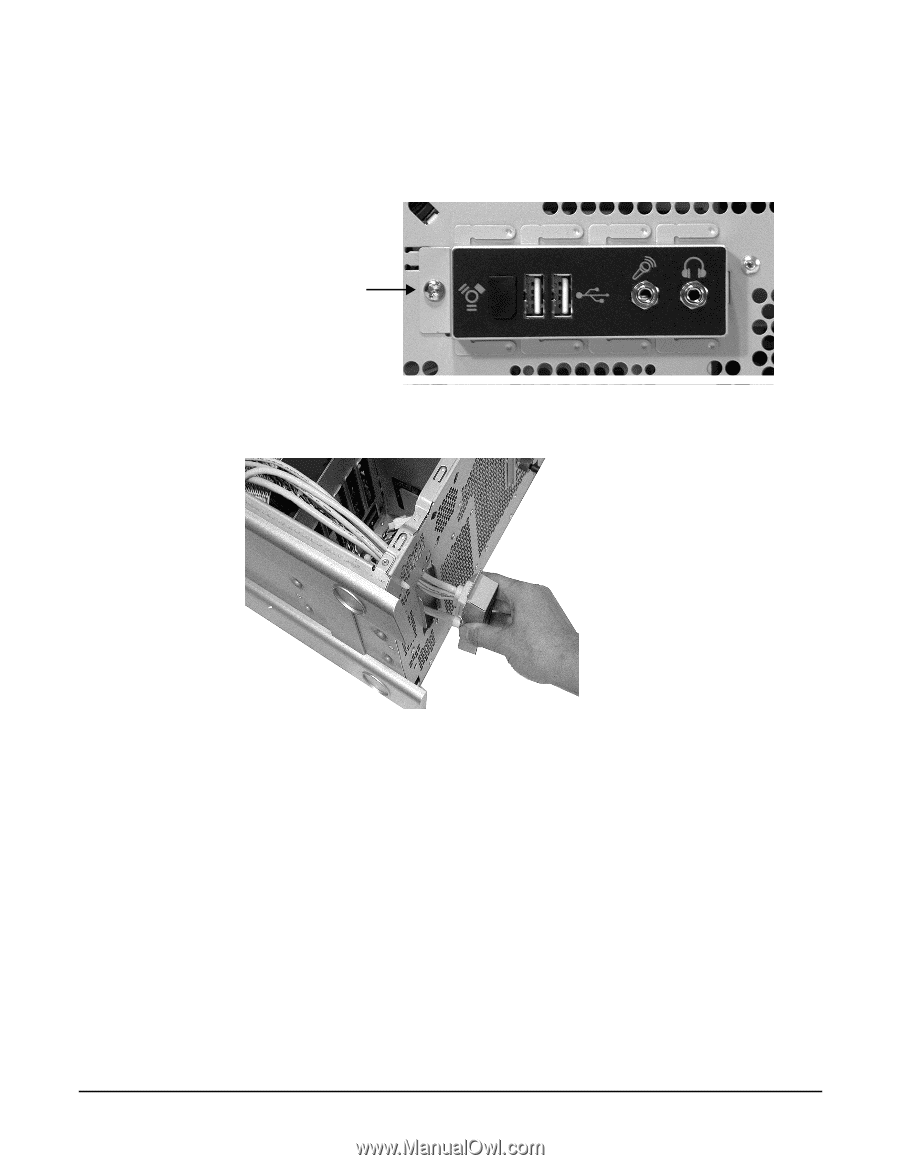
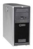
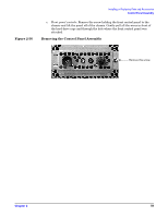
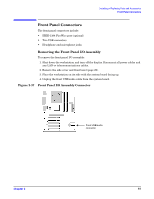
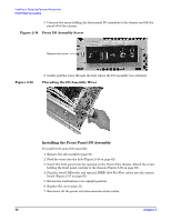
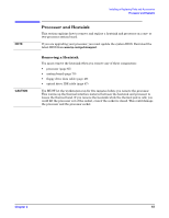
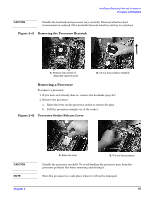
5. Unscrew the screw holding the front panel I/O assembly to the chassis and lift the panel off of the chassis. Figure 2-38 Front I/O Assembly Screw Figure 2-39 6. Gently pull the wires through the hole where the I/O assembly was attached. Threading the I/O Assembly Wires Installing the Front Panel I/O Assembly To install front panel I/O assembly: 1. Remove the old assembly (page 61). 2. Feed the wires into the hole (Figure 2-39 on page 62). 3. Insert the front panel into the opening on the front of the chassis. Attach the screw holding the front panel controls to the chassis (Figure 2-38 on page 62). 4. Plug the front USB/audio and optional IEEE-1394 FireWire cables into the system board (Figure 2-37 on page 61). 5. Return the workstation to its upright position. 6. Replace the cover (page 31). 7. Reconnect all the power and telecommunications cables.
-
 1
1 -
2
-
3
-
4
-
5
-
6
-
7
-
8
-
9
-
10
-
11
-
12
-
13
-
14
-
15
-
16
-
17
-
18
-
19
-
20
-
21
-
22
-
23
-
24
-
25
-
26
-
27
-
28
-
29
-
30
-
31
-
32
-
33
-
34
-
35
-
36
-
37
-
38
-
39
-
40
-
41
-
42
-
43
-
44
-
45
-
46
-
47
-
48
-
49
-
50
-
51
-
52
-
53
-
54
-
55
-
56
-
 57
57 -
 58
58 -
 59
59 -
 60
60 -
 61
61 -
 62
62 -
 63
63 -
 64
64 -
 65
65 -
 66
66 -
 67
67 -
68
-
69
-
70
-
71
-
72
-
73
-
74
-
75
-
76
-
77
-
78
-
79
-
80
-
81
-
82
-
83
-
84
-
85
-
86
-
87
-
88
-
89
-
90
-
91
-
92
-
93
-
94
-
95
-
96
-
97
-
98
-
99
-
100
-
101
-
102
-
103
-
104
-
105
-
106
-
107
-
108
-
109
-
110
-
111
-
112
-
113
-
114
-
115
-
116
-
117
-
118
 |
 |