HP Xw5000 hp workstation xw5000 Technical Reference (309233-001 10/02) - Page 68
Replacing the Processor and Heatsink, screws to 6 ins-lbs.
 |
UPC - 613326803318
View all HP Xw5000 manuals
Add to My Manuals
Save this manual to your list of manuals |
Page 68 highlights
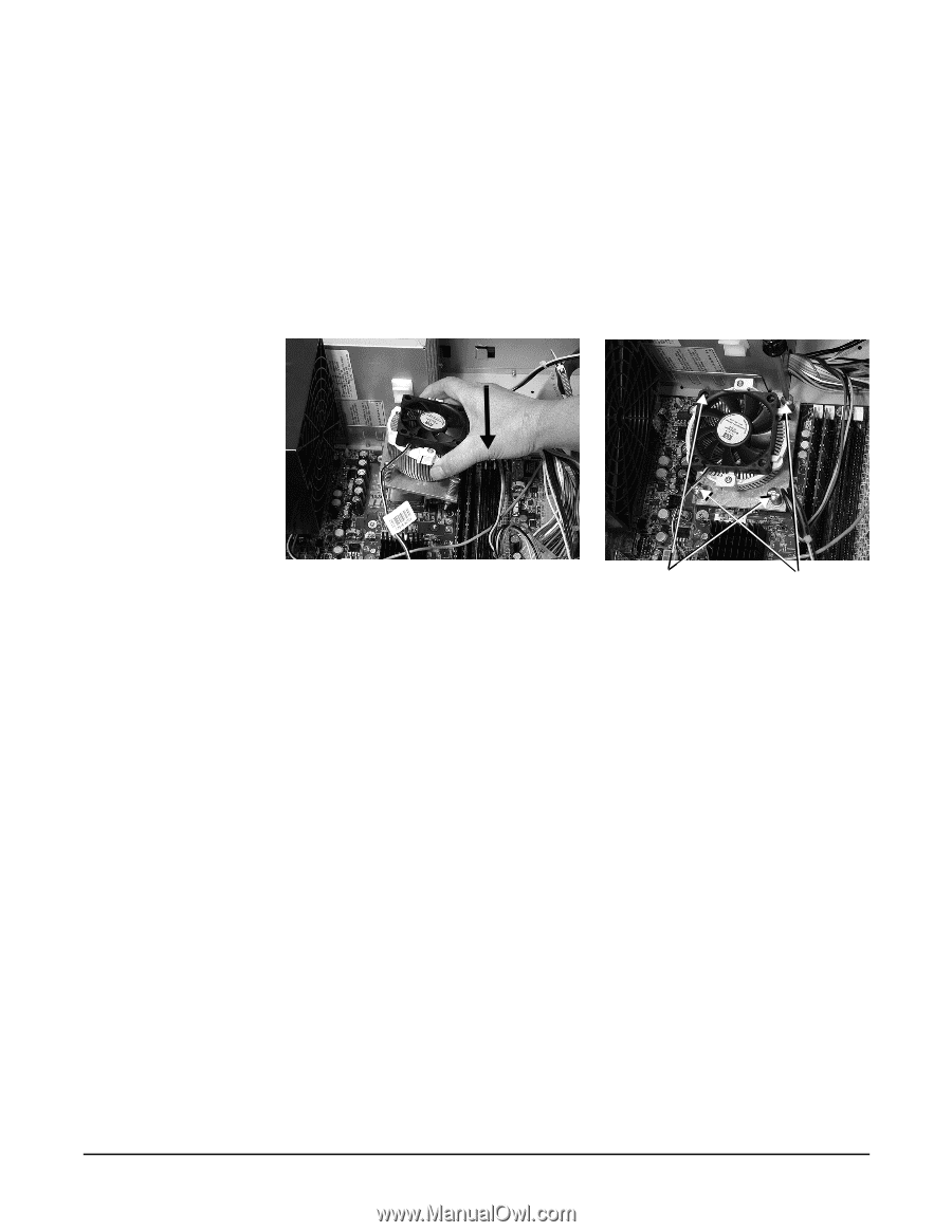
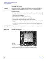
b. Attach the four captive processor heatsink screws: While carefully holding the system board back against the rear of the chassis, screw in the four processor screws slowly, making sure to tighten all the screws evenly. Tighten one pair of diagonally opposite screws until the screw shank settles on the system board, then tighten the remaining pair. Do not fully tighten one screw, then move on to the next. Tighten all of the screws a little at a time, making sure the processor remains level. If using a torque driver, tighten the screws to 6 ins-lbs. Figure 2-46 Replacing the Processor and Heatsink 5. Connect the heatsink fan connector to the system board (Figure 2-40 on page 64). 6. Replace the cover (page 31) and reconnect all power and telecommunications cables.
-
 1
1 -
2
-
3
-
4
-
5
-
6
-
7
-
8
-
9
-
10
-
11
-
12
-
13
-
14
-
15
-
16
-
17
-
18
-
19
-
20
-
21
-
22
-
23
-
24
-
25
-
26
-
27
-
28
-
29
-
30
-
31
-
32
-
33
-
34
-
35
-
36
-
37
-
38
-
39
-
40
-
41
-
42
-
43
-
44
-
45
-
46
-
47
-
48
-
49
-
50
-
51
-
52
-
53
-
54
-
55
-
56
-
57
-
58
-
59
-
60
-
61
-
62
-
 63
63 -
 64
64 -
 65
65 -
 66
66 -
 67
67 -
 68
68 -
 69
69 -
 70
70 -
 71
71 -
 72
72 -
 73
73 -
74
-
75
-
76
-
77
-
78
-
79
-
80
-
81
-
82
-
83
-
84
-
85
-
86
-
87
-
88
-
89
-
90
-
91
-
92
-
93
-
94
-
95
-
96
-
97
-
98
-
99
-
100
-
101
-
102
-
103
-
104
-
105
-
106
-
107
-
108
-
109
-
110
-
111
-
112
-
113
-
114
-
115
-
116
-
117
-
118
 |
 |