HP Xw5000 hp workstation xw5000 Technical Reference (309233-001 10/02) - Page 70
System Board, Removing the System Board
 |
UPC - 613326803318
View all HP Xw5000 manuals
Add to My Manuals
Save this manual to your list of manuals |
Page 70 highlights
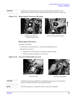
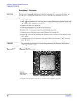
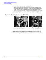
System Board Removing the System Board To remove the system board: 1. Shut down the workstation and turn off the display. Disconnect all power cables and any LAN or telecommunications cables. 2. Remove the side cover (page 29). 3. Place the workstation on its side for better access. 4. Remove the following cables and components (see Figure 1-3 on page 15 and Figure 2-1 on page 27): • IDE and SCSI (if applicable) connectors Disconnect cables from the system board and leave them in the chassis. Do not disconnect them from the devices. • AGP Card Support Assembly (if applicable) • Accessory and graphics cards • CD audio cable • Control panel, front USB/audio and optional IEEE-1394 FireWire connectors • Power cables • System Fan and housing • Power and data cables from floppy drive 5. The processor screws attach the system board to the chassis. Remove the heatsink (page 63) and processor (page 65) from the system board.
-
 1
1 -
2
-
3
-
4
-
5
-
6
-
7
-
8
-
9
-
10
-
11
-
12
-
13
-
14
-
15
-
16
-
17
-
18
-
19
-
20
-
21
-
22
-
23
-
24
-
25
-
26
-
27
-
28
-
29
-
30
-
31
-
32
-
33
-
34
-
35
-
36
-
37
-
38
-
39
-
40
-
41
-
42
-
43
-
44
-
45
-
46
-
47
-
48
-
49
-
50
-
51
-
52
-
53
-
54
-
55
-
56
-
57
-
58
-
59
-
60
-
61
-
62
-
63
-
64
-
 65
65 -
 66
66 -
 67
67 -
 68
68 -
 69
69 -
 70
70 -
 71
71 -
 72
72 -
 73
73 -
 74
74 -
 75
75 -
76
-
77
-
78
-
79
-
80
-
81
-
82
-
83
-
84
-
85
-
86
-
87
-
88
-
89
-
90
-
91
-
92
-
93
-
94
-
95
-
96
-
97
-
98
-
99
-
100
-
101
-
102
-
103
-
104
-
105
-
106
-
107
-
108
-
109
-
110
-
111
-
112
-
113
-
114
-
115
-
116
-
117
-
118
 |
 |
