HP Xw5000 hp workstation xw5000 Technical Reference (309233-001 10/02) - Page 108
Table A-16, Monitor, ATA/ATAPI IDE Standard Drive Cable, Connector and Icon, Signal, Connector
 |
UPC - 613326803318
View all HP Xw5000 manuals
Add to My Manuals
Save this manual to your list of manuals |
Page 108 highlights
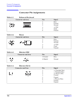
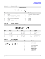
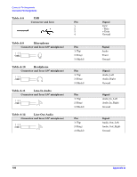
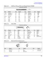
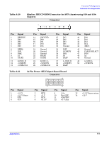
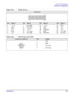
Table A-16 Monitor Connector and Icon Pin Signal 1 Red Analog 2 Green Analog 3 Blue Analog 4 Monitor ID 5 Ground Pin Signal 6 Ground 7 Ground 8 Ground 9 +5V DC 10 Ground Pin Signal 11 Monitor ID 12 DDC Serial Data 13 Horizontal Sync 14 Vertical Sync 15 DDC Serial Clock Table A-17 ATA/ATAPI (IDE) Standard Drive Cable Connector Pin Signal 1 Reset 2 Ground 3 DD7 4 DD8 5 DD6 6 DD9 7 DD5 8 DD10 9 DD4 10 DD11 11 DD3 12 DD12 13 DD2 14 DD13 Pin Signal 15 DD1 16 DD14 17 DD0 18 DD15 19 Ground 20 (Key) 21 DMARQ 22 Ground 23 DIOW 24 Ground 25 DIOR 26 Ground 27 IORDY 28 CSEL Pin Signal 29 DMAK 30 Ground 31 INTRQ 32 IOCS16 33 DA1 34 PDIAG (cable detect) 35 DA0 36 DA2 37 CS1FX 38 CS3FX 39 DASP 40 Ground
-
 1
1 -
2
-
3
-
4
-
5
-
6
-
7
-
8
-
9
-
10
-
11
-
12
-
13
-
14
-
15
-
16
-
17
-
18
-
19
-
20
-
21
-
22
-
23
-
24
-
25
-
26
-
27
-
28
-
29
-
30
-
31
-
32
-
33
-
34
-
35
-
36
-
37
-
38
-
39
-
40
-
41
-
42
-
43
-
44
-
45
-
46
-
47
-
48
-
49
-
50
-
51
-
52
-
53
-
54
-
55
-
56
-
57
-
58
-
59
-
60
-
61
-
62
-
63
-
64
-
65
-
66
-
67
-
68
-
69
-
70
-
71
-
72
-
73
-
74
-
75
-
76
-
77
-
78
-
79
-
80
-
81
-
82
-
83
-
84
-
85
-
86
-
87
-
88
-
89
-
90
-
91
-
92
-
93
-
94
-
95
-
96
-
97
-
98
-
99
-
100
-
101
-
102
-
 103
103 -
 104
104 -
 105
105 -
 106
106 -
 107
107 -
 108
108 -
 109
109 -
 110
110 -
 111
111 -
 112
112 -
 113
113 -
114
-
115
-
116
-
117
-
118
 |
 |
ȳººÃ¶·³²¸±¾º¸Å¿¿¾Áº¼Ãº·¿
»²¹¹¾É¶²³º¿¸¹ºÔµµ¸Æ¹¼¾¹¶µ
»ÈÈÊßÙÔã²»
ÀÁ¸
Table A-16
Monitor
Connector and Icon
Pin
Signal
Pin
Signal
Pin
Signal
1
2
3
Red Analog
Green Analog
Blue Analog
6
7
8
Ground
Ground
Ground
11
12
13
Monitor ID
DDC Serial Data
Horizontal Sync
4
5
Monitor ID
Ground
9
10
+5V DC
Ground
14
15
Vertical Sync
DDC Serial Clock
Table A-17
ATA/ATAPI (IDE) Standard Drive Cable
Connector
Pin
Signal
Pin
Signal
Pin
Signal
1
2
3
4
5
Reset
Ground
DD7
DD8
DD6
15
16
17
18
19
DD1
DD14
DD0
DD15
Ground
29
30
31
32
33
DMAK
Ground
INTRQ
IOCS16
DA1
6
7
8
9
10
DD9
DD5
DD10
DD4
DD11
20
21
22
23
24
(Key)
DMARQ
Ground
DIOW
Ground
34
35
36
37
38
PDIAG (cable detect)
DA0
DA2
CS1FX
CS3FX
11
12
13
14
DD3
DD12
DD2
DD13
25
26
27
28
DIOR
Ground
IORDY
CSEL
39
40
DASP
Ground