HP Xw5000 hp workstation xw5000 Technical Reference (309233-001 10/02) - Page 57
Control Panel Assembly, Removing the Control Panel Assembly
 |
UPC - 613326803318
View all HP Xw5000 manuals
Add to My Manuals
Save this manual to your list of manuals |
Page 57 highlights
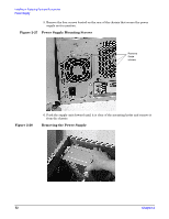
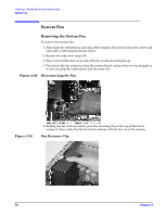
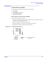
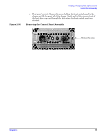
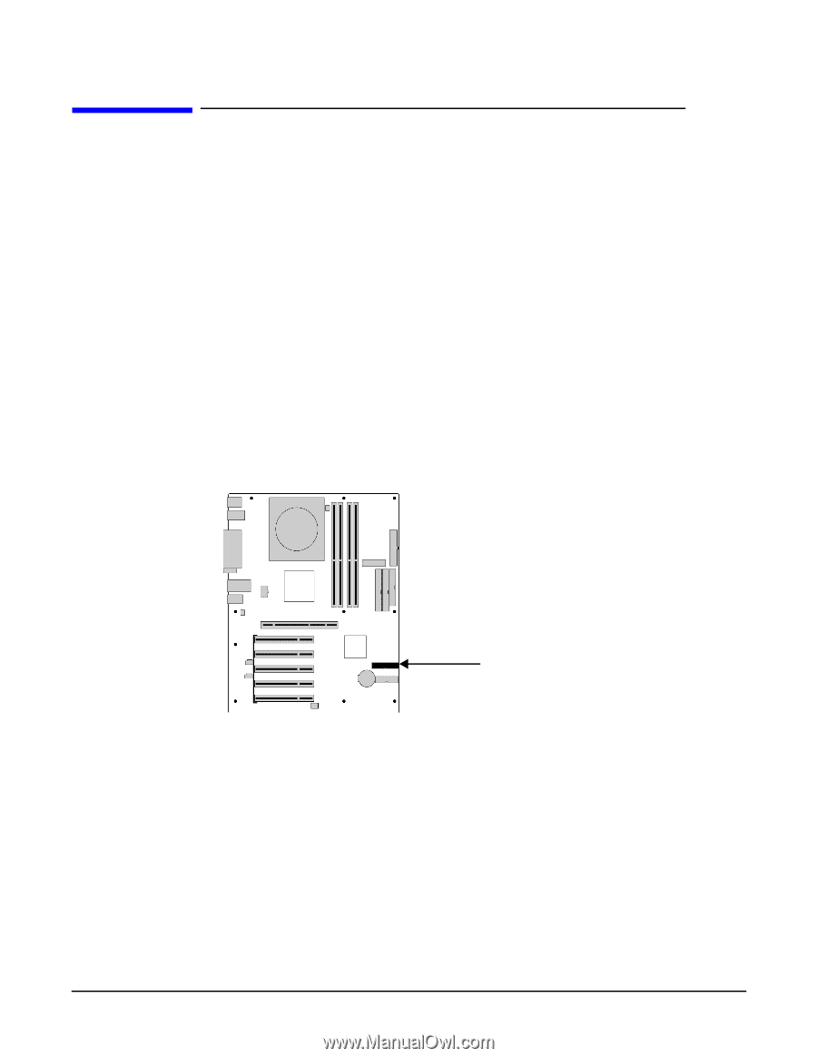
Control Panel Assembly The control panel assembly on the front of the system includes: • power button • reset button • power and disk-access LEDs • internal system speaker • chassis intrusion switch Removing the Control Panel Assembly To remove the control panel assembly: 1. Shut down the workstation and turn off the display. Disconnect all power cables and any LAN or telecommunications cables. 2. Remove the side cover and front bezel (page 29). 3. Place the workstation on its side with the system board facing up. 4. Remove the control panel cable from the system board. Figure 2-33 Control Panel Connector
-
 1
1 -
2
-
3
-
4
-
5
-
6
-
7
-
8
-
9
-
10
-
11
-
12
-
13
-
14
-
15
-
16
-
17
-
18
-
19
-
20
-
21
-
22
-
23
-
24
-
25
-
26
-
27
-
28
-
29
-
30
-
31
-
32
-
33
-
34
-
35
-
36
-
37
-
38
-
39
-
40
-
41
-
42
-
43
-
44
-
45
-
46
-
47
-
48
-
49
-
50
-
51
-
 52
52 -
 53
53 -
 54
54 -
 55
55 -
 56
56 -
 57
57 -
 58
58 -
 59
59 -
 60
60 -
 61
61 -
 62
62 -
63
-
64
-
65
-
66
-
67
-
68
-
69
-
70
-
71
-
72
-
73
-
74
-
75
-
76
-
77
-
78
-
79
-
80
-
81
-
82
-
83
-
84
-
85
-
86
-
87
-
88
-
89
-
90
-
91
-
92
-
93
-
94
-
95
-
96
-
97
-
98
-
99
-
100
-
101
-
102
-
103
-
104
-
105
-
106
-
107
-
108
-
109
-
110
-
111
-
112
-
113
-
114
-
115
-
116
-
117
-
118
 |
 |
¹º¿·½ÀÀ¾ºÁ¸³²¸ÂÃÄÀ½¶¾ºÁ¸±½²·¿¸½º´ Ŷ¶Ã¿¿³²¾Ã¿
»²¹¶³²Ãº¿·¹¾ÃºÔµµ¾¼×ÃÄ
ÂÆÇÈÉÊ˲±
µ·
Control Panel Assembly
The control panel assembly on the front of the system includes:
•
power button
•
reset button
•
power and disk-access LEDs
•
internal system speaker
•
chassis intrusion switch
Removing the Control Panel Assembly
To remove the control panel assembly:
1. Shut down the workstation and turn off the display. Disconnect all power cables and
any LAN or telecommunications cables.
2. Remove the side cover and front bezel (page 29).
3. Place the workstation on its side with the system board facing up.
4. Remove the control panel cable from the system board.
Figure 2-33
Control Panel Connector
à´»º·´Ó²ÒÅ»¶Ó²¿´»»¶¿º´·²
Òӹݽ²¾»²À¶·