HP Xw5000 hp workstation xw5000 Technical Reference (309233-001 10/02) - Page 60
Installing the Control Panel Assembly
 |
UPC - 613326803318
View all HP Xw5000 manuals
Add to My Manuals
Save this manual to your list of manuals |
Page 60 highlights
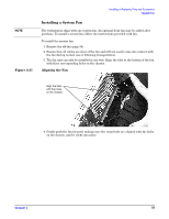
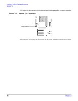
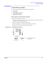
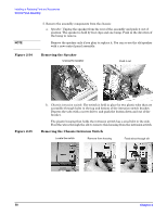
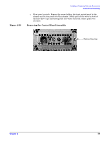
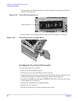
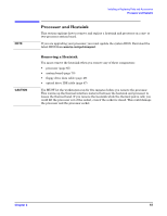
Installing the Control Panel Assembly To install the control panel assembly: 1. Remove the old assembly (page 57). 2. Attach the assembly components to the chassis: a. Chassis intrusion switch: Remove the switch housing from the switch/wire (reverse of above), then slide the switch through the hole where the front panel connectors were attached and through the opening in front of the hard drive bays. Re-install the switch housing, then Insert the switch into the bracket until it clicks (Figure 2-35 on page 58). Feed the control panel and speaker wires in front of the hard drive cage and into position. You must unplug the speaker from the rest of the assembly before feeding the wires into the chassis. b. Front panel controls: Insert the front panel into the slot on the chassis and attach the screw holding the front panel controls to the chassis (Figure 2-36 on page 59). c. Speaker: Attach the speaker to the chassis by sliding it in over the bump until it snaps into place (Figure 2-34 on page 58). Plug the speaker in to the assembly. 3. Plug the control panel cable into the system board (Figure 2-33 on page 57). 4. Return the workstation to its upright position. 5. Replace the cover (page 31). 6. Reconnect all the power and telecommunications cables.
-
 1
1 -
2
-
3
-
4
-
5
-
6
-
7
-
8
-
9
-
10
-
11
-
12
-
13
-
14
-
15
-
16
-
17
-
18
-
19
-
20
-
21
-
22
-
23
-
24
-
25
-
26
-
27
-
28
-
29
-
30
-
31
-
32
-
33
-
34
-
35
-
36
-
37
-
38
-
39
-
40
-
41
-
42
-
43
-
44
-
45
-
46
-
47
-
48
-
49
-
50
-
51
-
52
-
53
-
54
-
 55
55 -
 56
56 -
 57
57 -
 58
58 -
 59
59 -
 60
60 -
 61
61 -
 62
62 -
 63
63 -
 64
64 -
 65
65 -
66
-
67
-
68
-
69
-
70
-
71
-
72
-
73
-
74
-
75
-
76
-
77
-
78
-
79
-
80
-
81
-
82
-
83
-
84
-
85
-
86
-
87
-
88
-
89
-
90
-
91
-
92
-
93
-
94
-
95
-
96
-
97
-
98
-
99
-
100
-
101
-
102
-
103
-
104
-
105
-
106
-
107
-
108
-
109
-
110
-
111
-
112
-
113
-
114
-
115
-
116
-
117
-
118
 |
 |