HP Z210 HP Z210 CMT Workstation Maintenance and Service Guide - Page 110
CPU heatsink, Removing the CPU heatsink
 |
View all HP Z210 manuals
Add to My Manuals
Save this manual to your list of manuals |
Page 110 highlights
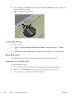
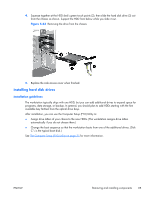
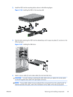
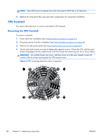
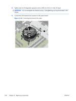
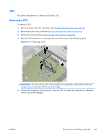
NOTE: Blue SATA ports (numbered zero and one) support SATA Gen 3 (6 Gbit/sec). 5. Replace all components that were removed in preparation for component installation. CPU heatsink This section describes how to remove and install a CPU heatsink. Removing the CPU heatsink To remove a heatsink: 1. Power down the workstation (see Predisassembly procedures on page 62). 2. Disconnect power from the workstation (see Predisassembly procedures on page 62). 3. Remove the side access panel (see Removing the side access panel on page 65). 4. Slowly and evenly loosen one pair of diagonally opposite screws (1) from the CPU until the screw shanks disengage from the system board, and then loosen the remaining pair (2) as shown below. CAUTION: Do not fully loosen one screw, and then move on to the next. Instead, loosen all screws a little at a time, ensuring that the CPU remains level. Figure 5-38 Loosening heatsink screws in sequence 98 Chapter 5 Replacing components ENWW
-
 1
1 -
2
-
3
-
4
-
5
-
6
-
7
-
8
-
9
-
10
-
11
-
12
-
13
-
14
-
15
-
16
-
17
-
18
-
19
-
20
-
21
-
22
-
23
-
24
-
25
-
26
-
27
-
28
-
29
-
30
-
31
-
32
-
33
-
34
-
35
-
36
-
37
-
38
-
39
-
40
-
41
-
42
-
43
-
44
-
45
-
46
-
47
-
48
-
49
-
50
-
51
-
52
-
53
-
54
-
55
-
56
-
57
-
58
-
59
-
60
-
61
-
62
-
63
-
64
-
65
-
66
-
67
-
68
-
69
-
70
-
71
-
72
-
73
-
74
-
75
-
76
-
77
-
78
-
79
-
80
-
81
-
82
-
83
-
84
-
85
-
86
-
87
-
88
-
89
-
90
-
91
-
92
-
93
-
94
-
95
-
96
-
97
-
98
-
99
-
100
-
101
-
102
-
103
-
104
-
 105
105 -
 106
106 -
 107
107 -
 108
108 -
 109
109 -
 110
110 -
 111
111 -
 112
112 -
 113
113 -
 114
114 -
 115
115 -
116
-
117
-
118
-
119
-
120
-
121
-
122
-
123
-
124
-
125
-
126
-
127
-
128
-
129
-
130
-
131
-
132
-
133
-
134
-
135
-
136
-
137
-
138
-
139
-
140
-
141
-
142
-
143
-
144
-
145
-
146
-
147
-
148
-
149
-
150
-
151
-
152
-
153
-
154
-
155
-
156
-
157
-
158
-
159
-
160
-
161
-
162
-
163
-
164
-
165
-
166
-
167
-
168
-
169
-
170
-
171
-
172
-
173
-
174
-
175
-
176
-
177
-
178
-
179
-
180
-
181
-
182
-
183
-
184
-
185
 |
 |