HP Z210 HP Z210 CMT Workstation Maintenance and Service Guide - Page 88
HP Z210 Manual
 |
View all HP Z210 manuals
Add to My Manuals
Save this manual to your list of manuals |
Page 88 highlights
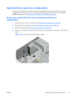
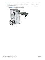
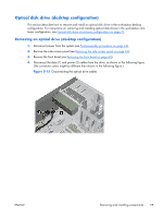
5. Press down on the green drive-lock release lever (1) and gently slide the drive out of the chassis (2). Figure 5-16 Removing the optical drive from chassis 6. If you plan to install another drive, remove the drive completely from the chassis (1) and remove the four guide screws from the drive (2) so that you can re-use the screws to install the new drive. (See Installing an optical drive (desktop configuration) on page 77 below.) Figure 5-17 Removing the optical drive screws 76 Chapter 5 Replacing components ENWW
-
 1
1 -
2
-
3
-
4
-
5
-
6
-
7
-
8
-
9
-
10
-
11
-
12
-
13
-
14
-
15
-
16
-
17
-
18
-
19
-
20
-
21
-
22
-
23
-
24
-
25
-
26
-
27
-
28
-
29
-
30
-
31
-
32
-
33
-
34
-
35
-
36
-
37
-
38
-
39
-
40
-
41
-
42
-
43
-
44
-
45
-
46
-
47
-
48
-
49
-
50
-
51
-
52
-
53
-
54
-
55
-
56
-
57
-
58
-
59
-
60
-
61
-
62
-
63
-
64
-
65
-
66
-
67
-
68
-
69
-
70
-
71
-
72
-
73
-
74
-
75
-
76
-
77
-
78
-
79
-
80
-
81
-
82
-
 83
83 -
 84
84 -
 85
85 -
 86
86 -
 87
87 -
 88
88 -
 89
89 -
 90
90 -
 91
91 -
 92
92 -
 93
93 -
94
-
95
-
96
-
97
-
98
-
99
-
100
-
101
-
102
-
103
-
104
-
105
-
106
-
107
-
108
-
109
-
110
-
111
-
112
-
113
-
114
-
115
-
116
-
117
-
118
-
119
-
120
-
121
-
122
-
123
-
124
-
125
-
126
-
127
-
128
-
129
-
130
-
131
-
132
-
133
-
134
-
135
-
136
-
137
-
138
-
139
-
140
-
141
-
142
-
143
-
144
-
145
-
146
-
147
-
148
-
149
-
150
-
151
-
152
-
153
-
154
-
155
-
156
-
157
-
158
-
159
-
160
-
161
-
162
-
163
-
164
-
165
-
166
-
167
-
168
-
169
-
170
-
171
-
172
-
173
-
174
-
175
-
176
-
177
-
178
-
179
-
180
-
181
-
182
-
183
-
184
-
185
 |
 |

5.
Press down on the green drive-lock release lever (1) and gently slide the drive out of the chassis
(2).
Figure 5-16
Removing the optical drive from chassis
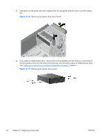
6.
If you plan to install another drive, remove the drive completely from the chassis (1) and remove
the four guide screws from the drive (2) so that you can re-use the screws to install the new drive.
(See
Installing an optical drive (desktop configuration)
on page
77
below.)
Figure 5-17
Removing the optical drive screws
76
Chapter 5
Replacing components
ENWW