HP Z210 HP Z210 CMT Workstation Maintenance and Service Guide - Page 173
System board designators, Designator, Silk screen, Component
 |
View all HP Z210 manuals
Add to My Manuals
Save this manual to your list of manuals |
Page 173 highlights
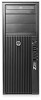
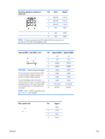
B System board designators This appendix describes the system board designators for this computer. Designator MTG1-MTG10 E15 E49 J9 J10 J20 J21 J22 J31 J32 J33 J41 J64 J65 J68 J83 J86 SW50 P1 P3 P5 P6 P8 P9 P24 P25 P26 Silk screen N/A E15 E49 J9 RJ/USB J10 QUAD USB J20 SLOT5 PCI J21 SLOT6 PCI J22 SLOT7 PCI J31 SLOT1 PCIe x1 J32 SLOT4 PCIe x16(4) J33 SLOT3 PCIe x4(1) J41 SLOT2 PCIe2 x16 75W DP DVI J68 PS2 KBD_MSE J83 AUD J86 SW50 CMOS P1 PWR P3 PWR CPU P5 PB/LED P6 P8 CHFAN P9 P24 FRONT USB P25 INTERNAL USB2 P26 INTERNAL USB3 Component Mounting holes Crisis recovery header/jumper Clear password header/jumper LAN/DUAL USB Quad rear USB PCI slot PCI slot PCI slot PCIe x1 slot PCIe x16(4) slot PCIe x4(1) PCIe2 x16 slot Display port connector DVI-I connector Stacked keyboard/mouse connector Triple stacked audio jacks Slot2 PCIe x16 retention clip Clear CMOS switch/push button Power supply connector (18-pin) CPU power connector (4-pin) Power button/HDD LED/Power LED switch/ Side access panel sensor/Temperature header Auxiliary graphics power connector Rear system fan Front fan header Front panel USB header Dual internal USB header Single internal USB header ENWW 161
-
 1
1 -
2
-
3
-
4
-
5
-
6
-
7
-
8
-
9
-
10
-
11
-
12
-
13
-
14
-
15
-
16
-
17
-
18
-
19
-
20
-
21
-
22
-
23
-
24
-
25
-
26
-
27
-
28
-
29
-
30
-
31
-
32
-
33
-
34
-
35
-
36
-
37
-
38
-
39
-
40
-
41
-
42
-
43
-
44
-
45
-
46
-
47
-
48
-
49
-
50
-
51
-
52
-
53
-
54
-
55
-
56
-
57
-
58
-
59
-
60
-
61
-
62
-
63
-
64
-
65
-
66
-
67
-
68
-
69
-
70
-
71
-
72
-
73
-
74
-
75
-
76
-
77
-
78
-
79
-
80
-
81
-
82
-
83
-
84
-
85
-
86
-
87
-
88
-
89
-
90
-
91
-
92
-
93
-
94
-
95
-
96
-
97
-
98
-
99
-
100
-
101
-
102
-
103
-
104
-
105
-
106
-
107
-
108
-
109
-
110
-
111
-
112
-
113
-
114
-
115
-
116
-
117
-
118
-
119
-
120
-
121
-
122
-
123
-
124
-
125
-
126
-
127
-
128
-
129
-
130
-
131
-
132
-
133
-
134
-
135
-
136
-
137
-
138
-
139
-
140
-
141
-
142
-
143
-
144
-
145
-
146
-
147
-
148
-
149
-
150
-
151
-
152
-
153
-
154
-
155
-
156
-
157
-
158
-
159
-
160
-
161
-
162
-
163
-
164
-
165
-
166
-
167
-
 168
168 -
 169
169 -
 170
170 -
 171
171 -
 172
172 -
 173
173 -
 174
174 -
 175
175 -
 176
176 -
 177
177 -
 178
178 -
179
-
180
-
181
-
182
-
183
-
184
-
185
 |
 |