HP Z210 HP Z210 CMT Workstation Maintenance and Service Guide - Page 170
Display port, Main power cable, P1, P3, Color, Signal, ML_Lane 3p
 |
View all HP Z210 manuals
Add to My Manuals
Save this manual to your list of manuals |
Page 170 highlights
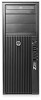
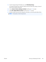
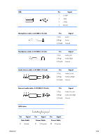
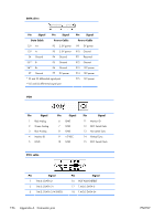
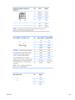
Display port 8 GND 9 ML_Lane 2(n) 10 ML_Lane 3(p) Main power cable, P1 18 Hot Plug Detect 19 DP_PWR Return 20 DP_PWR Pin Signal 1 5V 2 GND 3 GND 4 GND 5 GND 6 GND Pin Signal 78 PS_ON_L 910 5V 11 GND 12 V12-B Pin Signal 13 V12-B 14 V12-S 15 V12-S 16 17 11VSB 18 V12N CPU power cable, P3 Pin Color Signal 1 BLK GND 2 BLK GND 3 BLK with V12CPU BRN stripes 4 BLK with V12CPU BRN stripes CAUTION: Never connect the CPU power cable to the system board while power is on. If you do so, the system board can be damaged and the warranty voided. Be sure to distinguish between the CPU power cable that connects to the system board (4-pin white connector) and the Auxiliary graphics card power cable that connects to the PCIe x16 graphics card (6-pin black connector). 158 Appendix A Connector pins ENWW
-
 1
1 -
2
-
3
-
4
-
5
-
6
-
7
-
8
-
9
-
10
-
11
-
12
-
13
-
14
-
15
-
16
-
17
-
18
-
19
-
20
-
21
-
22
-
23
-
24
-
25
-
26
-
27
-
28
-
29
-
30
-
31
-
32
-
33
-
34
-
35
-
36
-
37
-
38
-
39
-
40
-
41
-
42
-
43
-
44
-
45
-
46
-
47
-
48
-
49
-
50
-
51
-
52
-
53
-
54
-
55
-
56
-
57
-
58
-
59
-
60
-
61
-
62
-
63
-
64
-
65
-
66
-
67
-
68
-
69
-
70
-
71
-
72
-
73
-
74
-
75
-
76
-
77
-
78
-
79
-
80
-
81
-
82
-
83
-
84
-
85
-
86
-
87
-
88
-
89
-
90
-
91
-
92
-
93
-
94
-
95
-
96
-
97
-
98
-
99
-
100
-
101
-
102
-
103
-
104
-
105
-
106
-
107
-
108
-
109
-
110
-
111
-
112
-
113
-
114
-
115
-
116
-
117
-
118
-
119
-
120
-
121
-
122
-
123
-
124
-
125
-
126
-
127
-
128
-
129
-
130
-
131
-
132
-
133
-
134
-
135
-
136
-
137
-
138
-
139
-
140
-
141
-
142
-
143
-
144
-
145
-
146
-
147
-
148
-
149
-
150
-
151
-
152
-
153
-
154
-
155
-
156
-
157
-
158
-
159
-
160
-
161
-
162
-
163
-
164
-
 165
165 -
 166
166 -
 167
167 -
 168
168 -
 169
169 -
 170
170 -
 171
171 -
 172
172 -
 173
173 -
 174
174 -
 175
175 -
176
-
177
-
178
-
179
-
180
-
181
-
182
-
183
-
184
-
185
 |
 |