HP Z210 HP Z210 CMT Workstation Maintenance and Service Guide - Page 93
Power connections
 |
View all HP Z210 manuals
Add to My Manuals
Save this manual to your list of manuals |
Page 93 highlights
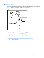
Power connections For help with identifying power cables, see the following figure and table. Ensure that all cables are routed or tied so they cannot interfere with the processor heatsink fans. Figure 5-22 Power connections Table 5-4 Power connector description Connector Description Item P1 Main power P12 P3 CPU power P13 P8, P9, P10 Hard disk drives P14 P6 Expansion graphics card Description Optical disk drive Optical disk drive 4-pin molex connector for legacy devices ENWW Removing and installing components 81
-
 1
1 -
2
-
3
-
4
-
5
-
6
-
7
-
8
-
9
-
10
-
11
-
12
-
13
-
14
-
15
-
16
-
17
-
18
-
19
-
20
-
21
-
22
-
23
-
24
-
25
-
26
-
27
-
28
-
29
-
30
-
31
-
32
-
33
-
34
-
35
-
36
-
37
-
38
-
39
-
40
-
41
-
42
-
43
-
44
-
45
-
46
-
47
-
48
-
49
-
50
-
51
-
52
-
53
-
54
-
55
-
56
-
57
-
58
-
59
-
60
-
61
-
62
-
63
-
64
-
65
-
66
-
67
-
68
-
69
-
70
-
71
-
72
-
73
-
74
-
75
-
76
-
77
-
78
-
79
-
80
-
81
-
82
-
83
-
84
-
85
-
86
-
87
-
 88
88 -
 89
89 -
 90
90 -
 91
91 -
 92
92 -
 93
93 -
 94
94 -
 95
95 -
 96
96 -
 97
97 -
 98
98 -
99
-
100
-
101
-
102
-
103
-
104
-
105
-
106
-
107
-
108
-
109
-
110
-
111
-
112
-
113
-
114
-
115
-
116
-
117
-
118
-
119
-
120
-
121
-
122
-
123
-
124
-
125
-
126
-
127
-
128
-
129
-
130
-
131
-
132
-
133
-
134
-
135
-
136
-
137
-
138
-
139
-
140
-
141
-
142
-
143
-
144
-
145
-
146
-
147
-
148
-
149
-
150
-
151
-
152
-
153
-
154
-
155
-
156
-
157
-
158
-
159
-
160
-
161
-
162
-
163
-
164
-
165
-
166
-
167
-
168
-
169
-
170
-
171
-
172
-
173
-
174
-
175
-
176
-
177
-
178
-
179
-
180
-
181
-
182
-
183
-
184
-
185
 |
 |
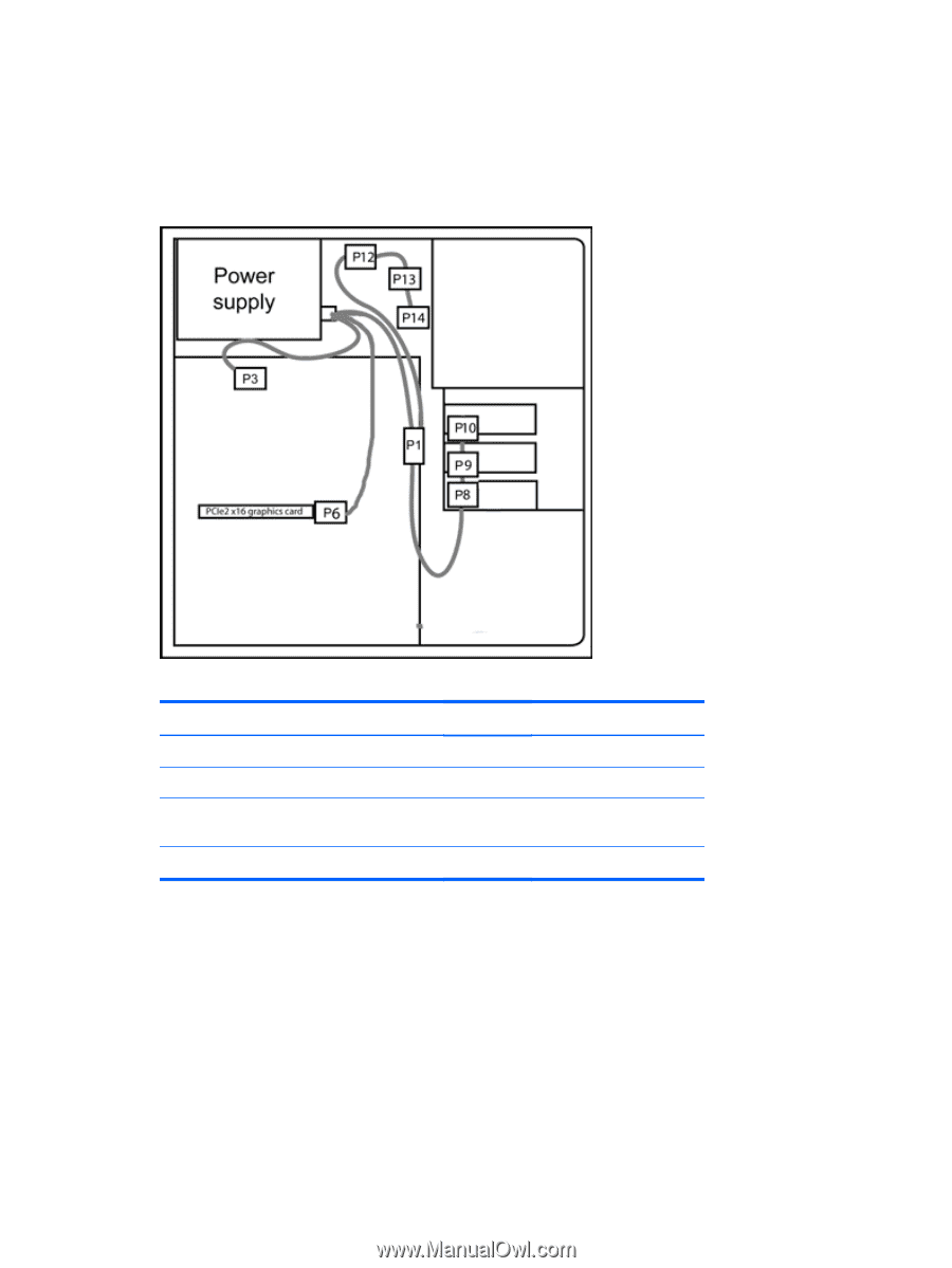
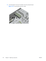
Power connections
For help with identifying power cables, see the following figure and table. Ensure that all cables are
routed or tied so they cannot interfere with the processor heatsink fans.
Figure 5-22
Power connections
Table 5-4
Power connector description
Connector
Description
Item
Description
P1
Main power
P12
Optical disk drive
P3
CPU power
P13
Optical disk drive
P8, P9, P10
Hard disk drives
P14
4–pin molex connector for
legacy devices
P6
Expansion graphics card
ENWW
Removing and installing components
81