HP Z210 HP Z210 CMT Workstation Maintenance and Service Guide - Page 99
Expansion card slot identification, Slot identification and description
 |
View all HP Z210 manuals
Add to My Manuals
Save this manual to your list of manuals |
Page 99 highlights
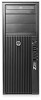
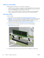
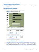
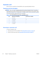
Expansion card slot identification This section identifies and describes workstation expansion card slots, and presents card configuration information. Slot identification and description The following figure identifies workstation expansion card slots. Figure 5-28 Identifying expansion card slots The following table describes the workstation PCIe card slots. Table 5-5 PCI slots Slot Type Slot power (per slot) Slot power (maximum) 1 PCIe2 - x8(4) 25W 2 PCIe2 - x16 75W 3 PCIe2 - x1 4 PCIe2 - x16(4) 5 PCIe2 - x1 10W 25W 10W 150W max for total power usage of all card slots 6 PCI 32b/33MHZ 25W 7 PCI 32b/33MHZ 25W NOTE: The x1, x4, and x16 designators describe the mechanical length of the slot. The number in parentheses lists the number of electrical PCIe lanes routed to the expansion slot. For example, x16(4) means that the expansion slot is mechanically a x16 length connector, with four PCIe lanes connected. ENWW Removing and installing components 87
-
 1
1 -
2
-
3
-
4
-
5
-
6
-
7
-
8
-
9
-
10
-
11
-
12
-
13
-
14
-
15
-
16
-
17
-
18
-
19
-
20
-
21
-
22
-
23
-
24
-
25
-
26
-
27
-
28
-
29
-
30
-
31
-
32
-
33
-
34
-
35
-
36
-
37
-
38
-
39
-
40
-
41
-
42
-
43
-
44
-
45
-
46
-
47
-
48
-
49
-
50
-
51
-
52
-
53
-
54
-
55
-
56
-
57
-
58
-
59
-
60
-
61
-
62
-
63
-
64
-
65
-
66
-
67
-
68
-
69
-
70
-
71
-
72
-
73
-
74
-
75
-
76
-
77
-
78
-
79
-
80
-
81
-
82
-
83
-
84
-
85
-
86
-
87
-
88
-
89
-
90
-
91
-
92
-
93
-
 94
94 -
 95
95 -
 96
96 -
 97
97 -
 98
98 -
 99
99 -
 100
100 -
 101
101 -
 102
102 -
 103
103 -
 104
104 -
105
-
106
-
107
-
108
-
109
-
110
-
111
-
112
-
113
-
114
-
115
-
116
-
117
-
118
-
119
-
120
-
121
-
122
-
123
-
124
-
125
-
126
-
127
-
128
-
129
-
130
-
131
-
132
-
133
-
134
-
135
-
136
-
137
-
138
-
139
-
140
-
141
-
142
-
143
-
144
-
145
-
146
-
147
-
148
-
149
-
150
-
151
-
152
-
153
-
154
-
155
-
156
-
157
-
158
-
159
-
160
-
161
-
162
-
163
-
164
-
165
-
166
-
167
-
168
-
169
-
170
-
171
-
172
-
173
-
174
-
175
-
176
-
177
-
178
-
179
-
180
-
181
-
182
-
183
-
184
-
185
 |
 |