HP Z210 HP Z210 CMT Workstation Maintenance and Service Guide - Page 115
System board, Removing the system board
 |
View all HP Z210 manuals
Add to My Manuals
Save this manual to your list of manuals |
Page 115 highlights
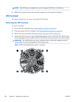
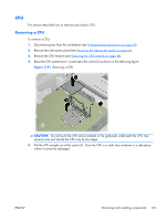
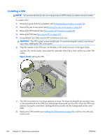
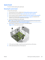
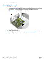
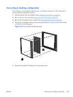
System board This section describes replacing the system board. Removing the system board To remove the system board: 1. Disconnect power from the workstation (see Predisassembly procedures on page 62). 2. Remove the side access panel (see Removing the side access panel on page 65). 3. Remove expansion boards and graphics cards (see Removing an expansion card on page 90). 4. Remove the CPU heatsink (see Removing the CPU heatsink on page 98). Note that the CPU heatsink screws also secure the system board to the chassis. 5. Disconnect all cabling from the system board. TIP: Make a note of the cable connections before disconnecting them from the system board. For more information, refer to Power connections on page 81. 6. Remove the ten mounting screws (1) as shown in the following figure. Figure 5-43 Removing the system board 7. Lift the system board slightly, and pull the board away from the rear of the chassis. 8. Lift the system board upward out of the chassis (2). ENWW Removing and installing components 103
-
 1
1 -
2
-
3
-
4
-
5
-
6
-
7
-
8
-
9
-
10
-
11
-
12
-
13
-
14
-
15
-
16
-
17
-
18
-
19
-
20
-
21
-
22
-
23
-
24
-
25
-
26
-
27
-
28
-
29
-
30
-
31
-
32
-
33
-
34
-
35
-
36
-
37
-
38
-
39
-
40
-
41
-
42
-
43
-
44
-
45
-
46
-
47
-
48
-
49
-
50
-
51
-
52
-
53
-
54
-
55
-
56
-
57
-
58
-
59
-
60
-
61
-
62
-
63
-
64
-
65
-
66
-
67
-
68
-
69
-
70
-
71
-
72
-
73
-
74
-
75
-
76
-
77
-
78
-
79
-
80
-
81
-
82
-
83
-
84
-
85
-
86
-
87
-
88
-
89
-
90
-
91
-
92
-
93
-
94
-
95
-
96
-
97
-
98
-
99
-
100
-
101
-
102
-
103
-
104
-
105
-
106
-
107
-
108
-
109
-
 110
110 -
 111
111 -
 112
112 -
 113
113 -
 114
114 -
 115
115 -
 116
116 -
 117
117 -
 118
118 -
 119
119 -
 120
120 -
121
-
122
-
123
-
124
-
125
-
126
-
127
-
128
-
129
-
130
-
131
-
132
-
133
-
134
-
135
-
136
-
137
-
138
-
139
-
140
-
141
-
142
-
143
-
144
-
145
-
146
-
147
-
148
-
149
-
150
-
151
-
152
-
153
-
154
-
155
-
156
-
157
-
158
-
159
-
160
-
161
-
162
-
163
-
164
-
165
-
166
-
167
-
168
-
169
-
170
-
171
-
172
-
173
-
174
-
175
-
176
-
177
-
178
-
179
-
180
-
181
-
182
-
183
-
184
-
185
 |
 |