Dell Precision T3400 User's Guide - Page 149
Power Supply DC Connector Pin Assignments, SAS Card Activity LED - cpu
 |
View all Dell Precision T3400 manuals
Add to My Manuals
Save this manual to your list of manuals |
Page 149 highlights
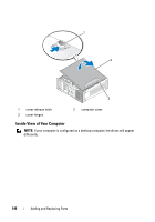
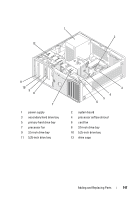
7 main power connector (POWER) 10 password reset jumper (RTCRST_PSWD) 13 PCI Express x16 card slot (SLOT2) 16 PCI card slots (SLOT5, SLOT6) 19 uDOC connector (UDOC1) 22 internal speaker connector (INT_SPKR) 8 SATA connectors (SATA2, SATA3, SATA4, SATA5) 11 chassis intrusion header (INTRUDER) 14 PCI Express x8 card slot wired as x4 (SLOT3) 17 SAS Card Activity LED (AUX_LED) 20 serial connector (SERIAL2) 23 processor fan connector (FAN_CPU) 9 FlexBay connector (USB1) 12 PCI card slot (SLOT1) 15 PCI Express x16 card slot (SLOT4) 18 floppy drive (FLOPPY) 21 card cage fan (FAN_CARD_ CAGE) 24 processor connector (CPU) Power Supply DC Connector Pin Assignments * 375-W PSU shown Adding and Replacing Parts 149
-
 1
1 -
2
-
3
-
4
-
5
-
6
-
7
-
8
-
9
-
10
-
11
-
12
-
13
-
14
-
15
-
16
-
17
-
18
-
19
-
20
-
21
-
22
-
23
-
24
-
25
-
26
-
27
-
28
-
29
-
30
-
31
-
32
-
33
-
34
-
35
-
36
-
37
-
38
-
39
-
40
-
41
-
42
-
43
-
44
-
45
-
46
-
47
-
48
-
49
-
50
-
51
-
52
-
53
-
54
-
55
-
56
-
57
-
58
-
59
-
60
-
61
-
62
-
63
-
64
-
65
-
66
-
67
-
68
-
69
-
70
-
71
-
72
-
73
-
74
-
75
-
76
-
77
-
78
-
79
-
80
-
81
-
82
-
83
-
84
-
85
-
86
-
87
-
88
-
89
-
90
-
91
-
92
-
93
-
94
-
95
-
96
-
97
-
98
-
99
-
100
-
101
-
102
-
103
-
104
-
105
-
106
-
107
-
108
-
109
-
110
-
111
-
112
-
113
-
114
-
115
-
116
-
117
-
118
-
119
-
120
-
121
-
122
-
123
-
124
-
125
-
126
-
127
-
128
-
129
-
130
-
131
-
132
-
133
-
134
-
135
-
136
-
137
-
138
-
139
-
140
-
141
-
142
-
143
-
 144
144 -
 145
145 -
 146
146 -
 147
147 -
 148
148 -
 149
149 -
 150
150 -
 151
151 -
 152
152 -
 153
153 -
 154
154 -
155
-
156
-
157
-
158
-
159
-
160
-
161
-
162
-
163
-
164
-
165
-
166
-
167
-
168
-
169
-
170
-
171
-
172
-
173
-
174
-
175
-
176
-
177
-
178
-
179
-
180
-
181
-
182
-
183
-
184
-
185
-
186
-
187
-
188
-
189
-
190
-
191
-
192
-
193
-
194
-
195
-
196
-
197
-
198
-
199
-
200
-
201
-
202
-
203
-
204
-
205
-
206
-
207
-
208
-
209
-
210
-
211
-
212
-
213
-
214
-
215
-
216
-
217
-
218
-
219
-
220
-
221
-
222
-
223
-
224
-
225
-
226
-
227
-
228
-
229
-
230
-
231
-
232
-
233
-
234
-
235
-
236
-
237
-
238
-
239
-
240
-
241
-
242
-
243
-
244
-
245
-
246
-
247
-
248
-
249
-
250
-
251
-
252
-
253
-
254
-
255
-
256
-
257
-
258
-
259
-
260
-
261
-
262
-
263
-
264
-
265
-
266
-
267
-
268
-
269
-
270
-
271
-
272
-
273
-
274
-
275
-
276
-
277
-
278
-
279
-
280
-
281
-
282
-
283
-
284
-
285
-
286
-
287
-
288
-
289
-
290
 |
 |

Adding and Replacing Parts
149
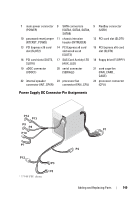
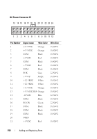
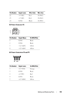
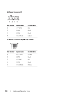
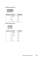
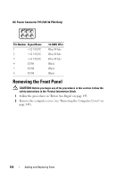
Power Supply DC Connector Pin Assignments
* 375-W PSU shown
7
main power connector
(POWER)
8
SATA connectors
(SATA2, SATA3, SATA4,
SATA5)
9
FlexBay connector
(USB1)
10
password reset jumper
(RTCRST_PSWD)
11
chassis intrusion
header (INTRUDER)
12
PCI card slot (SLOT1)
13
PCI Express x16 card
slot (SLOT2)
14
PCI Express x8 card
slot wired as x4
(SLOT3)
15
PCI Express x16 card
slot (SLOT4)
16
PCI card slots (SLOT5,
SLOT6)
17
SAS Card Activity LED
(AUX_LED)
18
floppy drive (FLOPPY)
19
uDOC connector
(UDOC1)
20
serial connector
(SERIAL2)
21
card cage fan
(FAN_CARD_
CAGE)
22
internal speaker
connector (INT_SPKR)
23
processor fan
connector (FAN_CPU)
24
processor connector
(CPU)