Dell Precision T3400 User's Guide - Page 155
Chassis Intrusion Switch, Removing the Chassis Intrusion Switch
 |
View all Dell Precision T3400 manuals
Add to My Manuals
Save this manual to your list of manuals |
Page 155 highlights
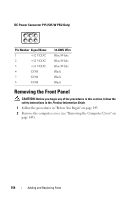
3 Lift the front panel release lever, and then slide the front panel towards the top of the computer to disengage and remove it. Chassis Intrusion Switch Removing the Chassis Intrusion Switch CAUTION: Before you begin any of the procedures in this section, follow the safety instructions in the Product Information Guide. 1 Follow the procedures in "Before You Begin" on page 143. 2 Remove the computer cover (see "Removing the Computer Cover" on page 145). 3 Disconnect the chassis intrusion switch cable from the system board (see "System Board Components" on page 148). Note the routing of the chassis intrusion switch cable. Chassis hooks may hold the cable in place inside the chassis. Adding and Replacing Parts 155
-
 1
1 -
2
-
3
-
4
-
5
-
6
-
7
-
8
-
9
-
10
-
11
-
12
-
13
-
14
-
15
-
16
-
17
-
18
-
19
-
20
-
21
-
22
-
23
-
24
-
25
-
26
-
27
-
28
-
29
-
30
-
31
-
32
-
33
-
34
-
35
-
36
-
37
-
38
-
39
-
40
-
41
-
42
-
43
-
44
-
45
-
46
-
47
-
48
-
49
-
50
-
51
-
52
-
53
-
54
-
55
-
56
-
57
-
58
-
59
-
60
-
61
-
62
-
63
-
64
-
65
-
66
-
67
-
68
-
69
-
70
-
71
-
72
-
73
-
74
-
75
-
76
-
77
-
78
-
79
-
80
-
81
-
82
-
83
-
84
-
85
-
86
-
87
-
88
-
89
-
90
-
91
-
92
-
93
-
94
-
95
-
96
-
97
-
98
-
99
-
100
-
101
-
102
-
103
-
104
-
105
-
106
-
107
-
108
-
109
-
110
-
111
-
112
-
113
-
114
-
115
-
116
-
117
-
118
-
119
-
120
-
121
-
122
-
123
-
124
-
125
-
126
-
127
-
128
-
129
-
130
-
131
-
132
-
133
-
134
-
135
-
136
-
137
-
138
-
139
-
140
-
141
-
142
-
143
-
144
-
145
-
146
-
147
-
148
-
149
-
 150
150 -
 151
151 -
 152
152 -
 153
153 -
 154
154 -
 155
155 -
 156
156 -
 157
157 -
 158
158 -
 159
159 -
 160
160 -
161
-
162
-
163
-
164
-
165
-
166
-
167
-
168
-
169
-
170
-
171
-
172
-
173
-
174
-
175
-
176
-
177
-
178
-
179
-
180
-
181
-
182
-
183
-
184
-
185
-
186
-
187
-
188
-
189
-
190
-
191
-
192
-
193
-
194
-
195
-
196
-
197
-
198
-
199
-
200
-
201
-
202
-
203
-
204
-
205
-
206
-
207
-
208
-
209
-
210
-
211
-
212
-
213
-
214
-
215
-
216
-
217
-
218
-
219
-
220
-
221
-
222
-
223
-
224
-
225
-
226
-
227
-
228
-
229
-
230
-
231
-
232
-
233
-
234
-
235
-
236
-
237
-
238
-
239
-
240
-
241
-
242
-
243
-
244
-
245
-
246
-
247
-
248
-
249
-
250
-
251
-
252
-
253
-
254
-
255
-
256
-
257
-
258
-
259
-
260
-
261
-
262
-
263
-
264
-
265
-
266
-
267
-
268
-
269
-
270
-
271
-
272
-
273
-
274
-
275
-
276
-
277
-
278
-
279
-
280
-
281
-
282
-
283
-
284
-
285
-
286
-
287
-
288
-
289
-
290
 |
 |

Adding and Replacing Parts
155
3
Lift the front panel release lever, and then slide the front panel towards
the top of the computer to disengage and remove it.
Chassis Intrusion Switch
Removing the Chassis Intrusion Switch
CAUTION:
Before you begin any of the procedures in this section, follow the
safety instructions in the
Product Information Guide
.
1
Follow the procedures in "Before You Begin" on page143.
2
Remove the computer cover (see "Removing the Computer Cover" on
page 145).
3
Disconnect the chassis intrusion switch cable from the system board (see
"System Board Components" on page 148).
Note the routing of the chassis intrusion switch cable. Chassis hooks may
hold the cable in place inside the chassis.