HP Xw4550 HP xw4550 Workstation - Service and Technical Reference Guide - Page 101
CAUTION, Do not touch the exposed thermal grease when handling the processor heatsink.
 |
UPC - 883585505951
View all HP Xw4550 manuals
Add to My Manuals
Save this manual to your list of manuals |
Page 101 highlights
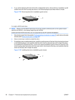
6. Lift the heatsink (2) from the processor. Figure 4-50 Removing the processor heatsink from the system board 7. Use alcohol and a soft cloth to clean all of the thermal interface residue from the heatsink and processor. CAUTION: Allow the alcohol on the processor and heatsink to dry completely. To replace the processor heatsink: 1. Disconnect power from the system (Predisassembly procedures on page 55). Remove the side chassis access panel (Side access panel on page 59). 2. Check for proper processor seating in the socket by carefully trying to lift the processor out of the socket with your fingers. A properly seated processor does not lift out of the socket. 3. If reusing the original heatsink, apply thermal grease to the center of the processor top surface. If using a new processor heatsink, do not apply thermal grease to the processor; the a new heatsink will have grease already applied to the heatsink surface. In this case, discard the thermal grease protective liner from the bottom of the new heatsink before installing. NOTE: Do not touch the exposed thermal grease when handling the processor heatsink. 4. Lower the processor heatsink onto the system board over the processor. 5. Carefully tighten the four screws a little at a time; do not fully tighten one screw and move onto the next. Be sure the processor remains level and be sure you do not overtighten the screws. If you have a torque-limited driver available, tighten the screws to 6 in.-lbs. CAUTION: Do not overtighten the screws. If you overtighten the screws, you risk stripping the threads in the system board tray. ENWW Steps for removing and replacing components 93
-
 1
1 -
2
-
3
-
4
-
5
-
6
-
7
-
8
-
9
-
10
-
11
-
12
-
13
-
14
-
15
-
16
-
17
-
18
-
19
-
20
-
21
-
22
-
23
-
24
-
25
-
26
-
27
-
28
-
29
-
30
-
31
-
32
-
33
-
34
-
35
-
36
-
37
-
38
-
39
-
40
-
41
-
42
-
43
-
44
-
45
-
46
-
47
-
48
-
49
-
50
-
51
-
52
-
53
-
54
-
55
-
56
-
57
-
58
-
59
-
60
-
61
-
62
-
63
-
64
-
65
-
66
-
67
-
68
-
69
-
70
-
71
-
72
-
73
-
74
-
75
-
76
-
77
-
78
-
79
-
80
-
81
-
82
-
83
-
84
-
85
-
86
-
87
-
88
-
89
-
90
-
91
-
92
-
93
-
94
-
95
-
 96
96 -
 97
97 -
 98
98 -
 99
99 -
 100
100 -
 101
101 -
 102
102 -
 103
103 -
 104
104 -
 105
105 -
 106
106 -
107
-
108
-
109
-
110
-
111
-
112
-
113
-
114
-
115
-
116
-
117
-
118
-
119
-
120
-
121
-
122
-
123
-
124
-
125
-
126
-
127
-
128
-
129
-
130
-
131
-
132
-
133
-
134
-
135
-
136
-
137
-
138
-
139
-
140
-
141
-
142
-
143
-
144
-
145
-
146
-
147
-
148
-
149
-
150
-
151
-
152
-
153
-
154
 |
 |
