HP Xw4550 HP xw4550 Workstation - Service and Technical Reference Guide - Page 69
Optional solenoid hood lock (Smart cover lock),
 |
UPC - 883585505951
View all HP Xw4550 manuals
Add to My Manuals
Save this manual to your list of manuals |
Page 69 highlights
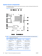
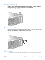
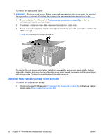
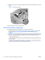
2. Disconnect the hood sensor connector (1) from system board. The hood sensor system board connector is located between the main power connector (P1) and the SATA Port0 connector on the system board (behind the installed hard drive, as shown in the inset (1) in the figure below). Figure 4-6 Removing the hood sensor 3. Slide the hood sensor forward, push it down, and remove it (2) from the chassis. . To replace the hood sensor, reverse the previous steps. Optional solenoid hood lock (Smart cover lock) To remove the hood lock: 1. Disconnect power from the system (Predisassembly procedures on page 55) and remove the side access panel (Side access panel on page 59). 2. Disconnect the solenoid hood lock cable (1) from the system board. 3. Using the FailSafe key (T-15 wrench), remove the two screws (2) from the back of the chassis as shown in the following figure. To purchase a FailSafe key, refer to the Hood lock (Smart cover lock) (optional) on page 45 section of this document for detailed information. ENWW Steps for removing and replacing components 61
-
 1
1 -
2
-
3
-
4
-
5
-
6
-
7
-
8
-
9
-
10
-
11
-
12
-
13
-
14
-
15
-
16
-
17
-
18
-
19
-
20
-
21
-
22
-
23
-
24
-
25
-
26
-
27
-
28
-
29
-
30
-
31
-
32
-
33
-
34
-
35
-
36
-
37
-
38
-
39
-
40
-
41
-
42
-
43
-
44
-
45
-
46
-
47
-
48
-
49
-
50
-
51
-
52
-
53
-
54
-
55
-
56
-
57
-
58
-
59
-
60
-
61
-
62
-
63
-
 64
64 -
 65
65 -
 66
66 -
 67
67 -
 68
68 -
 69
69 -
 70
70 -
 71
71 -
 72
72 -
 73
73 -
 74
74 -
75
-
76
-
77
-
78
-
79
-
80
-
81
-
82
-
83
-
84
-
85
-
86
-
87
-
88
-
89
-
90
-
91
-
92
-
93
-
94
-
95
-
96
-
97
-
98
-
99
-
100
-
101
-
102
-
103
-
104
-
105
-
106
-
107
-
108
-
109
-
110
-
111
-
112
-
113
-
114
-
115
-
116
-
117
-
118
-
119
-
120
-
121
-
122
-
123
-
124
-
125
-
126
-
127
-
128
-
129
-
130
-
131
-
132
-
133
-
134
-
135
-
136
-
137
-
138
-
139
-
140
-
141
-
142
-
143
-
144
-
145
-
146
-
147
-
148
-
149
-
150
-
151
-
152
-
153
-
154
 |
 |
