HP Xw4550 HP xw4550 Workstation - Service and Technical Reference Guide - Page 87
Required loading order, CAUTION
 |
UPC - 883585505951
View all HP Xw4550 manuals
Add to My Manuals
Save this manual to your list of manuals |
Page 87 highlights
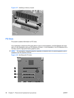
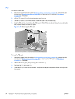
Required loading order Use the following illustration as a guide for installing memory modules: ● When installing a single DIMM only, install it in socket DIMM1A (item 1 in the illustration, and as shown on the system board label). ● Always install the first DIMM pair in sockets DIMM1A and DIMM1B (items 1 and 2, respectively, in the figure, and as shown on the system board label). ● Install the second DIMM pair in sockets DIMM2A and DIMM2B (item 3 in the figure, and as shown in the system board label). Figure 4-30 System board DIMM sockets To install a memory module: 1. Disconnect power from the system (Predisassembly procedures on page 55) and remove the side access panel (Side access panel on page 59). 2. Gently push outward on the socket locking levers to allow DIMMs to be inserted. CAUTION: DIMM contact connectors and system board DIMM slots are keyed to guide proper DIMM alignment. Always align the keyway on the DIMM contact connector to the key on the system board DIMM slot when installing DIMMs to prevent damage to the DIMMs. 3. Lower the DIMM straight down (1) and secure the socket levers (2) into their locked position over the ends of the memory modules. ENWW Steps for removing and replacing components 79
-
 1
1 -
2
-
3
-
4
-
5
-
6
-
7
-
8
-
9
-
10
-
11
-
12
-
13
-
14
-
15
-
16
-
17
-
18
-
19
-
20
-
21
-
22
-
23
-
24
-
25
-
26
-
27
-
28
-
29
-
30
-
31
-
32
-
33
-
34
-
35
-
36
-
37
-
38
-
39
-
40
-
41
-
42
-
43
-
44
-
45
-
46
-
47
-
48
-
49
-
50
-
51
-
52
-
53
-
54
-
55
-
56
-
57
-
58
-
59
-
60
-
61
-
62
-
63
-
64
-
65
-
66
-
67
-
68
-
69
-
70
-
71
-
72
-
73
-
74
-
75
-
76
-
77
-
78
-
79
-
80
-
81
-
 82
82 -
 83
83 -
 84
84 -
 85
85 -
 86
86 -
 87
87 -
 88
88 -
 89
89 -
 90
90 -
 91
91 -
 92
92 -
93
-
94
-
95
-
96
-
97
-
98
-
99
-
100
-
101
-
102
-
103
-
104
-
105
-
106
-
107
-
108
-
109
-
110
-
111
-
112
-
113
-
114
-
115
-
116
-
117
-
118
-
119
-
120
-
121
-
122
-
123
-
124
-
125
-
126
-
127
-
128
-
129
-
130
-
131
-
132
-
133
-
134
-
135
-
136
-
137
-
138
-
139
-
140
-
141
-
142
-
143
-
144
-
145
-
146
-
147
-
148
-
149
-
150
-
151
-
152
-
153
-
154
 |
 |
