HP Xw4550 HP xw4550 Workstation - Service and Technical Reference Guide - Page 76
and remove the front bezel
 |
UPC - 883585505951
View all HP Xw4550 manuals
Add to My Manuals
Save this manual to your list of manuals |
Page 76 highlights
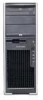
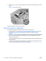
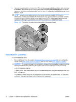
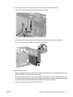
4. If replacing this drive with another drive, remove the four guide screws (2), shown in the following figure, and set them aside to be used in the replacement drive. Figure 4-16 Removing the guide screws To install an optical drive: NOTE: Always connect optical drives to the lowest numbered available SATA port, or immediately following any installed SATA hard drives. It is also important to connect all installed drives (both hard drives and optical drives) beginning at SATA0 and progressing through SATA3, leaving no gap in port numbering. 1. Disconnect power from the system (Predisassembly procedures on page 55), remove the side access panel (Side access panel on page 59) and remove the front bezel (Front Bezel on page 62). 2. If not already installed, Insert the four guide screws (1), as shown in the following figure, into the exterior of the drive housing. Figure 4-17 Installing the optical drive 68 Chapter 4 Removal and replacement procedures ENWW
-
 1
1 -
2
-
3
-
4
-
5
-
6
-
7
-
8
-
9
-
10
-
11
-
12
-
13
-
14
-
15
-
16
-
17
-
18
-
19
-
20
-
21
-
22
-
23
-
24
-
25
-
26
-
27
-
28
-
29
-
30
-
31
-
32
-
33
-
34
-
35
-
36
-
37
-
38
-
39
-
40
-
41
-
42
-
43
-
44
-
45
-
46
-
47
-
48
-
49
-
50
-
51
-
52
-
53
-
54
-
55
-
56
-
57
-
58
-
59
-
60
-
61
-
62
-
63
-
64
-
65
-
66
-
67
-
68
-
69
-
70
-
 71
71 -
 72
72 -
 73
73 -
 74
74 -
 75
75 -
 76
76 -
 77
77 -
 78
78 -
 79
79 -
 80
80 -
 81
81 -
82
-
83
-
84
-
85
-
86
-
87
-
88
-
89
-
90
-
91
-
92
-
93
-
94
-
95
-
96
-
97
-
98
-
99
-
100
-
101
-
102
-
103
-
104
-
105
-
106
-
107
-
108
-
109
-
110
-
111
-
112
-
113
-
114
-
115
-
116
-
117
-
118
-
119
-
120
-
121
-
122
-
123
-
124
-
125
-
126
-
127
-
128
-
129
-
130
-
131
-
132
-
133
-
134
-
135
-
136
-
137
-
138
-
139
-
140
-
141
-
142
-
143
-
144
-
145
-
146
-
147
-
148
-
149
-
150
-
151
-
152
-
153
-
154
 |
 |
