HP Xw4550 HP xw4550 Workstation - Service and Technical Reference Guide - Page 93
Front PCI card guide and optional fan removal,
 |
UPC - 883585505951
View all HP Xw4550 manuals
Add to My Manuals
Save this manual to your list of manuals |
Page 93 highlights
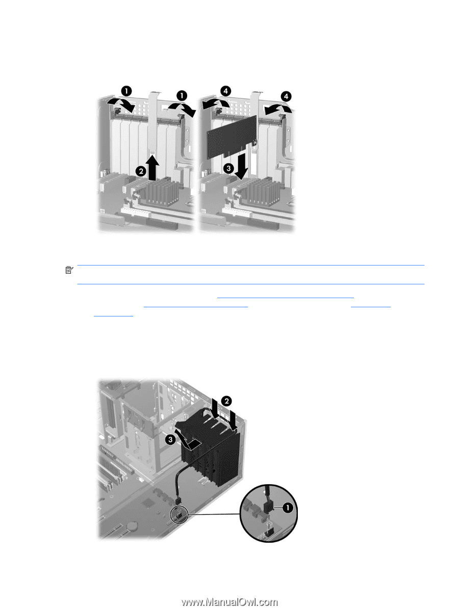
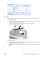
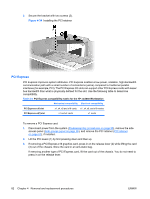
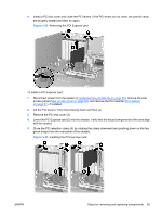
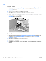
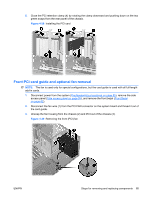
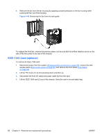
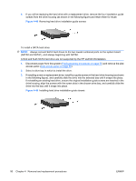
5. Close the PCI retention clamp (4) by rotating the clamp downward and pushing down on the two green snaps from the rear panel of the chassis. Figure 4-38 Installing the PCI card Front PCI card guide and optional fan removal NOTE: The fan is used only for special configurations, but the card guide is used with all full-length add-in cards. 1. Disconnect power from the system (Predisassembly procedures on page 55), remove the side access panel (Side access panel on page 59), and remove the front bezel (Front Bezel on page 62). 2. Disconnect the fan wire (1) from the PCI FAN connector on the system board and thread it out of the card guide. 3. Unsnap the fan housing from the chassis (2) and lift it out of the chassis (3). Figure 4-39 Removing the front (PCI) fan ENWW Steps for removing and replacing components 85
-
 1
1 -
2
-
3
-
4
-
5
-
6
-
7
-
8
-
9
-
10
-
11
-
12
-
13
-
14
-
15
-
16
-
17
-
18
-
19
-
20
-
21
-
22
-
23
-
24
-
25
-
26
-
27
-
28
-
29
-
30
-
31
-
32
-
33
-
34
-
35
-
36
-
37
-
38
-
39
-
40
-
41
-
42
-
43
-
44
-
45
-
46
-
47
-
48
-
49
-
50
-
51
-
52
-
53
-
54
-
55
-
56
-
57
-
58
-
59
-
60
-
61
-
62
-
63
-
64
-
65
-
66
-
67
-
68
-
69
-
70
-
71
-
72
-
73
-
74
-
75
-
76
-
77
-
78
-
79
-
80
-
81
-
82
-
83
-
84
-
85
-
86
-
87
-
 88
88 -
 89
89 -
 90
90 -
 91
91 -
 92
92 -
 93
93 -
 94
94 -
 95
95 -
 96
96 -
 97
97 -
 98
98 -
99
-
100
-
101
-
102
-
103
-
104
-
105
-
106
-
107
-
108
-
109
-
110
-
111
-
112
-
113
-
114
-
115
-
116
-
117
-
118
-
119
-
120
-
121
-
122
-
123
-
124
-
125
-
126
-
127
-
128
-
129
-
130
-
131
-
132
-
133
-
134
-
135
-
136
-
137
-
138
-
139
-
140
-
141
-
142
-
143
-
144
-
145
-
146
-
147
-
148
-
149
-
150
-
151
-
152
-
153
-
154
 |
 |