HP Xw4550 HP xw4550 Workstation - Service and Technical Reference Guide - Page 85
Memory, CAUTION
 |
UPC - 883585505951
View all HP Xw4550 manuals
Add to My Manuals
Save this manual to your list of manuals |
Page 85 highlights
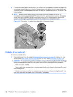
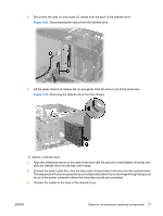
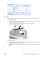
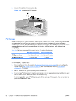
3. Remove the four screws (2) from the rear of the chassis with a Phillips screwdriver, and lift it (3) out of the chassis. Figure 4-28 Removing the system fan To replace the system fan assembly, reverse the previous steps. CAUTION: When replacing the system fan, be sure that the fan is situated so that the airflow direction arrow is pointing toward the rear of the chassis. Memory To remove a memory module: 1. Disconnect power from the system (Predisassembly procedures on page 55) and remove the side access panel (Side access panel on page 59). CAUTION: To ensure that memory modules are not damaged during removal or installation, power off the workstation and unplug the power cord from the AC power outlet. If you do not unplug the power cord while installing memory, your memory modules might be damaged and the system will not recognize the memory changes. 2. Gently push outward on the socket levers (1). ENWW Steps for removing and replacing components 77
-
 1
1 -
2
-
3
-
4
-
5
-
6
-
7
-
8
-
9
-
10
-
11
-
12
-
13
-
14
-
15
-
16
-
17
-
18
-
19
-
20
-
21
-
22
-
23
-
24
-
25
-
26
-
27
-
28
-
29
-
30
-
31
-
32
-
33
-
34
-
35
-
36
-
37
-
38
-
39
-
40
-
41
-
42
-
43
-
44
-
45
-
46
-
47
-
48
-
49
-
50
-
51
-
52
-
53
-
54
-
55
-
56
-
57
-
58
-
59
-
60
-
61
-
62
-
63
-
64
-
65
-
66
-
67
-
68
-
69
-
70
-
71
-
72
-
73
-
74
-
75
-
76
-
77
-
78
-
79
-
 80
80 -
 81
81 -
 82
82 -
 83
83 -
 84
84 -
 85
85 -
 86
86 -
 87
87 -
 88
88 -
 89
89 -
 90
90 -
91
-
92
-
93
-
94
-
95
-
96
-
97
-
98
-
99
-
100
-
101
-
102
-
103
-
104
-
105
-
106
-
107
-
108
-
109
-
110
-
111
-
112
-
113
-
114
-
115
-
116
-
117
-
118
-
119
-
120
-
121
-
122
-
123
-
124
-
125
-
126
-
127
-
128
-
129
-
130
-
131
-
132
-
133
-
134
-
135
-
136
-
137
-
138
-
139
-
140
-
141
-
142
-
143
-
144
-
145
-
146
-
147
-
148
-
149
-
150
-
151
-
152
-
153
-
154
 |
 |
