HP Xw4550 HP xw4550 Workstation - Service and Technical Reference Guide - Page 64
System board components, HP xw4550 Workstation.
 |
UPC - 883585505951
View all HP Xw4550 manuals
Add to My Manuals
Save this manual to your list of manuals |
Page 64 highlights
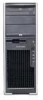
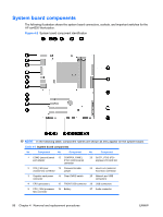
System board components The following illustration shows the system board connectors, sockets, and important switches for the HP xw4550 Workstation. Figure 4-2 System board component identification NOTE: In the following table, component names are shown as they appear on the system board. Table 4-3 System board components No. Component No. Component No. Component 1 COM2 (second) serial 12 CONTROL PANEL port adapter (Front control panel) connector 23 SLOT1_PCIE (PCIexpress) x16 card slot 2 SYS_FAN (rear 13 Password Enable chassis fan) connector jumper 24 Hood Lock (solenoid hood lock) connector 3 Graphics card power connector 14 Clear CMOS switch 25 Network and USB connectors 4 CPU (processor ) 15 FRONT USB connector 26 USB connectors 5 CPU_FAN (processor 16 Battery fan) connector 27 Audio connector 56 Chapter 4 Removal and replacement procedures ENWW
-
 1
1 -
2
-
3
-
4
-
5
-
6
-
7
-
8
-
9
-
10
-
11
-
12
-
13
-
14
-
15
-
16
-
17
-
18
-
19
-
20
-
21
-
22
-
23
-
24
-
25
-
26
-
27
-
28
-
29
-
30
-
31
-
32
-
33
-
34
-
35
-
36
-
37
-
38
-
39
-
40
-
41
-
42
-
43
-
44
-
45
-
46
-
47
-
48
-
49
-
50
-
51
-
52
-
53
-
54
-
55
-
56
-
57
-
58
-
 59
59 -
 60
60 -
 61
61 -
 62
62 -
 63
63 -
 64
64 -
 65
65 -
 66
66 -
 67
67 -
 68
68 -
 69
69 -
70
-
71
-
72
-
73
-
74
-
75
-
76
-
77
-
78
-
79
-
80
-
81
-
82
-
83
-
84
-
85
-
86
-
87
-
88
-
89
-
90
-
91
-
92
-
93
-
94
-
95
-
96
-
97
-
98
-
99
-
100
-
101
-
102
-
103
-
104
-
105
-
106
-
107
-
108
-
109
-
110
-
111
-
112
-
113
-
114
-
115
-
116
-
117
-
118
-
119
-
120
-
121
-
122
-
123
-
124
-
125
-
126
-
127
-
128
-
129
-
130
-
131
-
132
-
133
-
134
-
135
-
136
-
137
-
138
-
139
-
140
-
141
-
142
-
143
-
144
-
145
-
146
-
147
-
148
-
149
-
150
-
151
-
152
-
153
-
154
 |
 |
