HP Xw4550 HP xw4550 Workstation - Service and Technical Reference Guide - Page 84
System fan assembly, access panel
 |
UPC - 883585505951
View all HP Xw4550 manuals
Add to My Manuals
Save this manual to your list of manuals |
Page 84 highlights
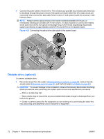
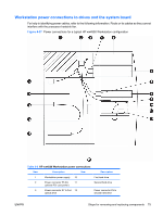
Table 4-4 HP xw4550 Workstation power connections (continued) Item Description Item Description 4 Power connector P8 to 13 second optical drive Power connector P1 to system board 5 First optical drive 14 PCI slot (shows optional IEEE 1394 PCI card with optional adapter cable connected to power connector P6) 6 Second optical drive 15 Optional graphics card (with power connection to system board graphics power connector P4) NOTE: Disables workstation integrated graphics capability when installed. 7 Power connector P9 to 16 diskette drive 6-pin system board connector P4 for graphics card auxiliary power cable. 8 Diskette drive 17 Workstation system board 9 Power connector P4 to first 18 hard drive 4-pin power connector P3 to system board P3 System fan assembly To remove the system fan assembly: 1. Disconnect power from the system (Predisassembly procedures on page 55) and remove the side access panel (Side access panel on page 59). 2. Disconnect the fan plug (1) from the system board. 76 Chapter 4 Removal and replacement procedures ENWW
-
 1
1 -
2
-
3
-
4
-
5
-
6
-
7
-
8
-
9
-
10
-
11
-
12
-
13
-
14
-
15
-
16
-
17
-
18
-
19
-
20
-
21
-
22
-
23
-
24
-
25
-
26
-
27
-
28
-
29
-
30
-
31
-
32
-
33
-
34
-
35
-
36
-
37
-
38
-
39
-
40
-
41
-
42
-
43
-
44
-
45
-
46
-
47
-
48
-
49
-
50
-
51
-
52
-
53
-
54
-
55
-
56
-
57
-
58
-
59
-
60
-
61
-
62
-
63
-
64
-
65
-
66
-
67
-
68
-
69
-
70
-
71
-
72
-
73
-
74
-
75
-
76
-
77
-
78
-
 79
79 -
 80
80 -
 81
81 -
 82
82 -
 83
83 -
 84
84 -
 85
85 -
 86
86 -
 87
87 -
 88
88 -
 89
89 -
90
-
91
-
92
-
93
-
94
-
95
-
96
-
97
-
98
-
99
-
100
-
101
-
102
-
103
-
104
-
105
-
106
-
107
-
108
-
109
-
110
-
111
-
112
-
113
-
114
-
115
-
116
-
117
-
118
-
119
-
120
-
121
-
122
-
123
-
124
-
125
-
126
-
127
-
128
-
129
-
130
-
131
-
132
-
133
-
134
-
135
-
136
-
137
-
138
-
139
-
140
-
141
-
142
-
143
-
144
-
145
-
146
-
147
-
148
-
149
-
150
-
151
-
152
-
153
-
154
 |
 |
