HP Xw4550 HP xw4550 Workstation - Service and Technical Reference Guide - Page 103
System board,
 |
UPC - 883585505951
View all HP Xw4550 manuals
Add to My Manuals
Save this manual to your list of manuals |
Page 103 highlights
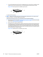
3. To properly align the processor with the socket, orient the small triangle image located on one corner of the processor circuit board to the matching triangle image on one corner of the processor socket (see illustration below). With all processor pins properly aligned, press the processor straight down into the socket until the processor is seated. Figure 4-52 Seating and locking the processor 4. Ensure that the underside of the processor is sitting level with the top of the processor socket, then press lightly on the top of the processor while simultaneously closing the socket lever to the locked position (as shown in the above illustration). 5. Check for proper processor seating in the socket by carefully trying to lift the processor out of the socket with your fingers. A properly seated processor does not lift out of the socket. System board To remove the system board: 1. Disconnect power from the system (Predisassembly procedures on page 55) and remove the side access panel (Side access panel on page 59), remove all expansion boards, and graphics cards. 2. Disconnect all cabling from the system board and remove all I/O cards. NOTE: Make note of the cable connections before disconnecting them from the system board. Refer to Workstation power connections to drives and the system board on page 75 for more information. NOTE: It is not necessary to remove the processor heatsink before removing the system board. 3. Press the release tab (1) as shown in the following illustration. ENWW Steps for removing and replacing components 95
-
 1
1 -
2
-
3
-
4
-
5
-
6
-
7
-
8
-
9
-
10
-
11
-
12
-
13
-
14
-
15
-
16
-
17
-
18
-
19
-
20
-
21
-
22
-
23
-
24
-
25
-
26
-
27
-
28
-
29
-
30
-
31
-
32
-
33
-
34
-
35
-
36
-
37
-
38
-
39
-
40
-
41
-
42
-
43
-
44
-
45
-
46
-
47
-
48
-
49
-
50
-
51
-
52
-
53
-
54
-
55
-
56
-
57
-
58
-
59
-
60
-
61
-
62
-
63
-
64
-
65
-
66
-
67
-
68
-
69
-
70
-
71
-
72
-
73
-
74
-
75
-
76
-
77
-
78
-
79
-
80
-
81
-
82
-
83
-
84
-
85
-
86
-
87
-
88
-
89
-
90
-
91
-
92
-
93
-
94
-
95
-
96
-
97
-
 98
98 -
 99
99 -
 100
100 -
 101
101 -
 102
102 -
 103
103 -
 104
104 -
 105
105 -
 106
106 -
 107
107 -
 108
108 -
109
-
110
-
111
-
112
-
113
-
114
-
115
-
116
-
117
-
118
-
119
-
120
-
121
-
122
-
123
-
124
-
125
-
126
-
127
-
128
-
129
-
130
-
131
-
132
-
133
-
134
-
135
-
136
-
137
-
138
-
139
-
140
-
141
-
142
-
143
-
144
-
145
-
146
-
147
-
148
-
149
-
150
-
151
-
152
-
153
-
154
 |
 |
