HP Xw4550 HP xw4550 Workstation - Service and Technical Reference Guide - Page 61
Screws, Special handling of components,
 |
UPC - 883585505951
View all HP Xw4550 manuals
Add to My Manuals
Save this manual to your list of manuals |
Page 61 highlights
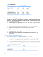
Screws The screws used in the workstation are not interchangeable. They might have standard or metric threads and might be of different lengths. If an incorrect screw is used during the reassembly process, it can damage the unit. Hewlett-Packard strongly recommends that all screws removed during disassembly be kept with the removed part, and then returned to their proper locations. NOTE: Metric screws have a black finish. American National Standards Institute (ANSI) screws have a silver finish. As each subassembly is removed from the workstation, place the subassembly away from the work area to prevent damage. If necessary, additional drive guide screws are provided on the system chassis. There are eight Metric screws (1), as shown in the following figure, located on the chassis near the 5.25-inch optical drive bays. These screws can be used to mount additional optical drives or an optional diskette drive. There are four ANSI screws (2), as shown in the following figure, located on the chassis near the hard drive. These screws can be used to mount additional hard drives in the 3.5" hard drive cage. NOTE: Metric (black) and ANSI (silver) screws are not interchangeable. Figure 4-1 Metric and ANSI screw identification 1 Metric screws Used for optical and diskette drives. 2 ANSI screws Used for hard drives. Special handling of components The following components require special handling when servicing the workstation. ENWW Service considerations 53
-
 1
1 -
2
-
3
-
4
-
5
-
6
-
7
-
8
-
9
-
10
-
11
-
12
-
13
-
14
-
15
-
16
-
17
-
18
-
19
-
20
-
21
-
22
-
23
-
24
-
25
-
26
-
27
-
28
-
29
-
30
-
31
-
32
-
33
-
34
-
35
-
36
-
37
-
38
-
39
-
40
-
41
-
42
-
43
-
44
-
45
-
46
-
47
-
48
-
49
-
50
-
51
-
52
-
53
-
54
-
55
-
 56
56 -
 57
57 -
 58
58 -
 59
59 -
 60
60 -
 61
61 -
 62
62 -
 63
63 -
 64
64 -
 65
65 -
 66
66 -
67
-
68
-
69
-
70
-
71
-
72
-
73
-
74
-
75
-
76
-
77
-
78
-
79
-
80
-
81
-
82
-
83
-
84
-
85
-
86
-
87
-
88
-
89
-
90
-
91
-
92
-
93
-
94
-
95
-
96
-
97
-
98
-
99
-
100
-
101
-
102
-
103
-
104
-
105
-
106
-
107
-
108
-
109
-
110
-
111
-
112
-
113
-
114
-
115
-
116
-
117
-
118
-
119
-
120
-
121
-
122
-
123
-
124
-
125
-
126
-
127
-
128
-
129
-
130
-
131
-
132
-
133
-
134
-
135
-
136
-
137
-
138
-
139
-
140
-
141
-
142
-
143
-
144
-
145
-
146
-
147
-
148
-
149
-
150
-
151
-
152
-
153
-
154
 |
 |
