HP Xw4550 HP xw4550 Workstation - Service and Technical Reference Guide - Page 71
Front panel I/O device assembly,
 |
UPC - 883585505951
View all HP Xw4550 manuals
Add to My Manuals
Save this manual to your list of manuals |
Page 71 highlights
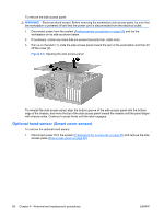
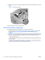
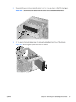
1. Disconnect power from the system (Predisassembly procedures on page 55) and remove the front bezel (Front Bezel on page 62). 2. Gently push the subpanel (1) out the back of the front bezel. 3. Remove the desired bezel blank by applying outward pressure on the subpanel (1) and pulling the blank (2) away. Figure 4-9 Removing the bezel blanks NOTE: The bezel blanks are keyed to assist you in replacing the blanks. Also, the subpanel can be rotated 90 degrees to install the optical drives in desktop orientation if desired. Front panel I/O device assembly To remove the front panel I/O device assembly: 1. Disconnect power from the system (Predisassembly procedures on page 55), remove the side access panel (Side access panel on page 59), and remove the front bezel (Front Bezel on page 62). 2. Unlatch the plastic snap that secures the cables inside the chassis and disconnect the front panel I/O device assembly cables from the system board. 3. Remove the two smaller Torx screws (1) that hold the front panel I/O device assembly (3) and bracket to the chassis. 4. Remove the two larger Torx screws (2) that hold the front panel I/O device assembly (3) to the bracket. 5. Separate the bracket away from the front panel I/O device assembly. 6. Pull the front panel I/O device assembly out about two inches away (4) from the chassis. ENWW Steps for removing and replacing components 63
-
 1
1 -
2
-
3
-
4
-
5
-
6
-
7
-
8
-
9
-
10
-
11
-
12
-
13
-
14
-
15
-
16
-
17
-
18
-
19
-
20
-
21
-
22
-
23
-
24
-
25
-
26
-
27
-
28
-
29
-
30
-
31
-
32
-
33
-
34
-
35
-
36
-
37
-
38
-
39
-
40
-
41
-
42
-
43
-
44
-
45
-
46
-
47
-
48
-
49
-
50
-
51
-
52
-
53
-
54
-
55
-
56
-
57
-
58
-
59
-
60
-
61
-
62
-
63
-
64
-
65
-
 66
66 -
 67
67 -
 68
68 -
 69
69 -
 70
70 -
 71
71 -
 72
72 -
 73
73 -
 74
74 -
 75
75 -
 76
76 -
77
-
78
-
79
-
80
-
81
-
82
-
83
-
84
-
85
-
86
-
87
-
88
-
89
-
90
-
91
-
92
-
93
-
94
-
95
-
96
-
97
-
98
-
99
-
100
-
101
-
102
-
103
-
104
-
105
-
106
-
107
-
108
-
109
-
110
-
111
-
112
-
113
-
114
-
115
-
116
-
117
-
118
-
119
-
120
-
121
-
122
-
123
-
124
-
125
-
126
-
127
-
128
-
129
-
130
-
131
-
132
-
133
-
134
-
135
-
136
-
137
-
138
-
139
-
140
-
141
-
142
-
143
-
144
-
145
-
146
-
147
-
148
-
149
-
150
-
151
-
152
-
153
-
154
 |
 |
