HP Xw4550 HP xw4550 Workstation - Service and Technical Reference Guide - Page 72
HP Xw4550 - Workstation - 2 GB RAM Manual
 |
UPC - 883585505951
View all HP Xw4550 manuals
Add to My Manuals
Save this manual to your list of manuals |
Page 72 highlights
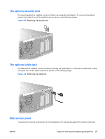
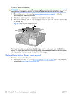
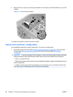
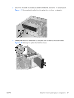
7. Pull the front panel cables through the chassis and out the front of the workstation. You might have to slide the cables out one at a time. Figure 4-10 Removing the front panel I/O device assembly To replace the front panel I/O device assembly: 1. Thread each front panel I/O device assembly cable through the same holes from which they were removed. 2. Push the front panel I/O device assembly into the chassis. Using your fingers, orient the cables so that there is enough room form the front panel I/O device assembly to easily fit in its slot. 3. Loosely put the bracket on the front panel I/O device assembly and hook the bracket to the chassis. 4. Screw the bracket to the front panel I/O device assembly and screw the bracket to the chassis. 5. Connect the front audio cable to (1). Connect the front USB cable to (2). Connect the front control panel cable to (3). If an IEEE-1394 card is installed, connect the front IEEE-1394 cable to the card. Figure 4-11 Attaching front panel I/O device assembly cables 64 Chapter 4 Removal and replacement procedures ENWW
-
 1
1 -
2
-
3
-
4
-
5
-
6
-
7
-
8
-
9
-
10
-
11
-
12
-
13
-
14
-
15
-
16
-
17
-
18
-
19
-
20
-
21
-
22
-
23
-
24
-
25
-
26
-
27
-
28
-
29
-
30
-
31
-
32
-
33
-
34
-
35
-
36
-
37
-
38
-
39
-
40
-
41
-
42
-
43
-
44
-
45
-
46
-
47
-
48
-
49
-
50
-
51
-
52
-
53
-
54
-
55
-
56
-
57
-
58
-
59
-
60
-
61
-
62
-
63
-
64
-
65
-
66
-
 67
67 -
 68
68 -
 69
69 -
 70
70 -
 71
71 -
 72
72 -
 73
73 -
 74
74 -
 75
75 -
 76
76 -
 77
77 -
78
-
79
-
80
-
81
-
82
-
83
-
84
-
85
-
86
-
87
-
88
-
89
-
90
-
91
-
92
-
93
-
94
-
95
-
96
-
97
-
98
-
99
-
100
-
101
-
102
-
103
-
104
-
105
-
106
-
107
-
108
-
109
-
110
-
111
-
112
-
113
-
114
-
115
-
116
-
117
-
118
-
119
-
120
-
121
-
122
-
123
-
124
-
125
-
126
-
127
-
128
-
129
-
130
-
131
-
132
-
133
-
134
-
135
-
136
-
137
-
138
-
139
-
140
-
141
-
142
-
143
-
144
-
145
-
146
-
147
-
148
-
149
-
150
-
151
-
152
-
153
-
154
 |
 |
