HP Xw4550 HP xw4550 Workstation - Service and Technical Reference Guide - Page 65
Steps for removing and replacing components, Disassembly order, Safety and Regulatory Information - workstation review
 |
UPC - 883585505951
View all HP Xw4550 manuals
Add to My Manuals
Save this manual to your list of manuals |
Page 65 highlights
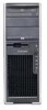
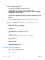
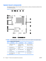
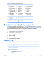
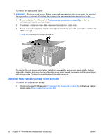
Table 4-3 System board components (continued) No. Component No. Component 6 Memory module sockets 17 INTERNAL USB connector 7 Floppy (diskette) drive 18 SPK (speaker) connector connector 8 Power Connector P1 19 FRONT AUDIO (main power to sysetm connector board) 9 HOOD SENSE (optional chassis intrusion switch) connector 20 AUX_IN (auxiliary) audio connector 10 SATA (SATA0 - SATA3) port connectors 21 SLOT3 & SLOT4 PCI 32/33 card slots 11 PCI FAN (front chassis 22 SLOT2_PCIE (PCI- fan) Express) x4(1) card slot No. Component 28 DVI-D integrated video connector 29 Serial port (top) connector 30 VGA (bottom) connector 31 Power Connector (processor power) connector Steps for removing and replacing components This section discusses the procedures necessary to remove and install various hardware components on your workstation. Review the safety and precautions and the Service considerations on page 50, as well as the Safety and Regulatory Information, before servicing or upgrading your system. Follow these safety and procedural steps when servicing your workstation: 1. Read all safety information and precautions. 2. Locate and clear a suitable work area. 3. Shut down the system and remove power from the unit. 4. Gather your tools. 5. Service your workstation. 6. Restore power to your workstation. Disassembly order Use the following table to determine the sequence in which to remove the major components. Predisassembly (Predisassembly procedures on page 55) Security lock (The optional security lock on page 59) Cable lock (The optional cable lock on page 59) Side access panel (Side access panel on page 59) ENWW Steps for removing and replacing components 57
-
 1
1 -
2
-
3
-
4
-
5
-
6
-
7
-
8
-
9
-
10
-
11
-
12
-
13
-
14
-
15
-
16
-
17
-
18
-
19
-
20
-
21
-
22
-
23
-
24
-
25
-
26
-
27
-
28
-
29
-
30
-
31
-
32
-
33
-
34
-
35
-
36
-
37
-
38
-
39
-
40
-
41
-
42
-
43
-
44
-
45
-
46
-
47
-
48
-
49
-
50
-
51
-
52
-
53
-
54
-
55
-
56
-
57
-
58
-
59
-
 60
60 -
 61
61 -
 62
62 -
 63
63 -
 64
64 -
 65
65 -
 66
66 -
 67
67 -
 68
68 -
 69
69 -
 70
70 -
71
-
72
-
73
-
74
-
75
-
76
-
77
-
78
-
79
-
80
-
81
-
82
-
83
-
84
-
85
-
86
-
87
-
88
-
89
-
90
-
91
-
92
-
93
-
94
-
95
-
96
-
97
-
98
-
99
-
100
-
101
-
102
-
103
-
104
-
105
-
106
-
107
-
108
-
109
-
110
-
111
-
112
-
113
-
114
-
115
-
116
-
117
-
118
-
119
-
120
-
121
-
122
-
123
-
124
-
125
-
126
-
127
-
128
-
129
-
130
-
131
-
132
-
133
-
134
-
135
-
136
-
137
-
138
-
139
-
140
-
141
-
142
-
143
-
144
-
145
-
146
-
147
-
148
-
149
-
150
-
151
-
152
-
153
-
154
 |
 |
