HP Xw4550 HP xw4550 Workstation - Service and Technical Reference Guide - Page 79
CAUTION, Installing the optical drive
 |
UPC - 883585505951
View all HP Xw4550 manuals
Add to My Manuals
Save this manual to your list of manuals |
Page 79 highlights
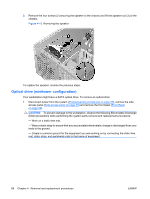
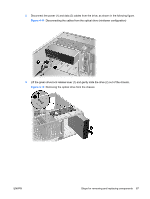
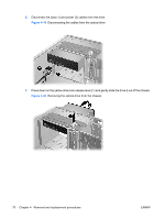
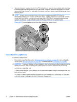
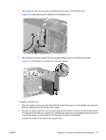
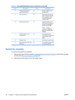
4. If the drive is to be replaced, remove the four installation guide screws (2), as shown in the following figure, and set them aside. Figure 4-21 Removing the optical drive screws To install an optical drive: 1. Disconnect power from the system (Predisassembly procedures on page 55), remove the side access panel (Side access panel on page 59) and remove the front bezel (Front Bezel on page 62). 2. If reinstalling an original optical drive, go to the next step. If installing a new drive or replacing the original drive with replacement drive, insert four installation guide screws into the drive housing (1), as shown in the following figure. Figure 4-22 Installing the optical drive 3. Align the guide screws with the grooves in the desired drive bay and gently slide the drive into the workstation until it snaps into place (2), as shown in the preceding figure. CAUTION: Ensure that the optical drive is secure by pulling to see if the drive can become easily disengaged. Failure to do so can cause damage to the drive when moving the workstation. ENWW Steps for removing and replacing components 71
-
 1
1 -
2
-
3
-
4
-
5
-
6
-
7
-
8
-
9
-
10
-
11
-
12
-
13
-
14
-
15
-
16
-
17
-
18
-
19
-
20
-
21
-
22
-
23
-
24
-
25
-
26
-
27
-
28
-
29
-
30
-
31
-
32
-
33
-
34
-
35
-
36
-
37
-
38
-
39
-
40
-
41
-
42
-
43
-
44
-
45
-
46
-
47
-
48
-
49
-
50
-
51
-
52
-
53
-
54
-
55
-
56
-
57
-
58
-
59
-
60
-
61
-
62
-
63
-
64
-
65
-
66
-
67
-
68
-
69
-
70
-
71
-
72
-
73
-
 74
74 -
 75
75 -
 76
76 -
 77
77 -
 78
78 -
 79
79 -
 80
80 -
 81
81 -
 82
82 -
 83
83 -
 84
84 -
85
-
86
-
87
-
88
-
89
-
90
-
91
-
92
-
93
-
94
-
95
-
96
-
97
-
98
-
99
-
100
-
101
-
102
-
103
-
104
-
105
-
106
-
107
-
108
-
109
-
110
-
111
-
112
-
113
-
114
-
115
-
116
-
117
-
118
-
119
-
120
-
121
-
122
-
123
-
124
-
125
-
126
-
127
-
128
-
129
-
130
-
131
-
132
-
133
-
134
-
135
-
136
-
137
-
138
-
139
-
140
-
141
-
142
-
143
-
144
-
145
-
146
-
147
-
148
-
149
-
150
-
151
-
152
-
153
-
154
 |
 |
