HP Xw4550 HP xw4550 Workstation - Service and Technical Reference Guide - Page 77
Optical drive (desktop configuration), CAUTION,
 |
UPC - 883585505951
View all HP Xw4550 manuals
Add to My Manuals
Save this manual to your list of manuals |
Page 77 highlights
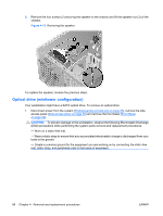
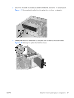
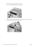
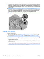
3. Align the screws with the grooves in the drive bay and gently slide the drive into the workstation until it snaps into place (2). CAUTION: Ensure that the optical drive is securely seated by pulling on it to see if the drive can become easily disengaged. Failure to securely seat the drive might cause damage to the drive when moving the workstation. 4. Connect the power cable (2) first, then the data cable (in that order) to the drive and system board. This will allow any possible accumulated static electricity to discharge through the ground circuit of the power connector before the drive data circuits are connected. NOTE: SATA ports on the system board must always be populated beginning with SATA0, and leaving no gaps as additional ports are connected. Connect the optical drive data cable to the lowest numbered SATA port still available. Figure 4-18 Connecting the optical drive data cable Optical drive (desktop configuration) To remove an optical drive: 1. Disconnect power from the system (Predisassembly procedures on page 55), remove the side access panel (Side access panel on page 59) and remove the front bezel (Front Bezel on page 62). CAUTION: To prevent damage to the workstation, observe the following Electrostatic Discharge (ESD) precautions while performing the system parts removal and replacement procedures: - Work on a static-free mat. - Wear a static strap to ensure that any accumulated electrostatic charge is discharged from your body to the ground. - Create a common ground for the equipment you are working on by connecting the static-free mat, static strap, and peripheral units to that piece of equipment. ENWW Steps for removing and replacing components 69
-
 1
1 -
2
-
3
-
4
-
5
-
6
-
7
-
8
-
9
-
10
-
11
-
12
-
13
-
14
-
15
-
16
-
17
-
18
-
19
-
20
-
21
-
22
-
23
-
24
-
25
-
26
-
27
-
28
-
29
-
30
-
31
-
32
-
33
-
34
-
35
-
36
-
37
-
38
-
39
-
40
-
41
-
42
-
43
-
44
-
45
-
46
-
47
-
48
-
49
-
50
-
51
-
52
-
53
-
54
-
55
-
56
-
57
-
58
-
59
-
60
-
61
-
62
-
63
-
64
-
65
-
66
-
67
-
68
-
69
-
70
-
71
-
 72
72 -
 73
73 -
 74
74 -
 75
75 -
 76
76 -
 77
77 -
 78
78 -
 79
79 -
 80
80 -
 81
81 -
 82
82 -
83
-
84
-
85
-
86
-
87
-
88
-
89
-
90
-
91
-
92
-
93
-
94
-
95
-
96
-
97
-
98
-
99
-
100
-
101
-
102
-
103
-
104
-
105
-
106
-
107
-
108
-
109
-
110
-
111
-
112
-
113
-
114
-
115
-
116
-
117
-
118
-
119
-
120
-
121
-
122
-
123
-
124
-
125
-
126
-
127
-
128
-
129
-
130
-
131
-
132
-
133
-
134
-
135
-
136
-
137
-
138
-
139
-
140
-
141
-
142
-
143
-
144
-
145
-
146
-
147
-
148
-
149
-
150
-
151
-
152
-
153
-
154
 |
 |
