IBM 4840-544 Service Guide
IBM 4840-544 - SurePOS 500 - 256 MB RAM Manual
 |
View all IBM 4840-544 manuals
Add to My Manuals
Save this manual to your list of manuals |
IBM 4840-544 manual content summary:
- IBM 4840-544 | Service Guide - Page 1
SurePOS 500 Series Hardware Service Guide for Models 533, 543, 544, 553, 563, 564, 573, and 5A3 August 3, 2006 SY27-0417-02 - IBM 4840-544 | Service Guide - Page 2
- IBM 4840-544 | Service Guide - Page 3
SurePOS 500 Series Hardware Service Guide for Models 533, 543, 544, 553, 563, 564, 573, and 5A3 August 3, 2006 SY27-0417-02 - IBM 4840-544 | Service Guide - Page 4
using this information and the product it supports, be sure to read "Safety and environmental notices" on page xiii and the general information in Appendix E, "Notices," on page 191. | Third Edition (June 2006) | This edition applies to the IBM® SurePOS 500, machine type 4840, Models 533, 543, 544 - IBM 4840-544 | Service Guide - Page 5
xxii Chapter 1. Introducing the IBM SurePOS 500 Series Models 533, 543, 544, 553, 563, 564, 573, and 5A3 1 SurePOS 500 Models 5x3 and 544/564 2 SurePOS 500 Models 5x3 and 544/564 Features 3 Standard features 3 Optional features 4 Dual-display feature 4 PC Card subsystem 5 System software - IBM 4840-544 | Service Guide - Page 6
Service Diskette (for the 5x3 models 30 Using the IBM Diagnostics for Peripherals (for the 5x3 models 31 Using the IBM Diagnostics for POS System Units and Peripherals (for the 5x4 models 31 Diagnostic wrap plugs 31 Chapter 4. Removing and replacing FRUs for the SurePOS 500 Models 5x3 and 544 - IBM 4840-544 | Service Guide - Page 7
and replacing 113 Distributed customer display - disassembling 118 IBM 4610 SureMark printers - removing and replacing 121 4610 137 CANPOS keypad assembly 138 CANPOS keyboard logic card 141 CANPOS keyboard with MSR 142 Appendix A. D. SurePOS 500 Models 5x3 and 544/564 tips 189 Contents v - IBM 4840-544 | Service Guide - Page 8
August 3, 2006 Tools 189 Appendix E. Notices 191 Intel software license agreement (final, single user 193 Copyright license 193 Ownership of software and copyrights 193 Limited media warranty 193 Termination of this agreement 194 Applicable laws 194 Government restricted rights 194 - IBM 4840-544 | Service Guide - Page 9
2006 Figures 1. SurePOS 500 Models 5x3 and 544/564 configuration with video adapter or jumper location 68 48. Removing the fansink 70 49. Memory socket location 72 50. Memory module removal 73 51. Removing the PC card adapter slot blank 74 52. Removing a PC card adapter 75 © Copyright IBM - IBM 4840-544 | Service Guide - Page 10
from the full-size keyboard integration tray 94 71. Removing the 4820 SurePoint Solution display cable and covers 95 72. Removing the SurePOS 500 Models 5x3 and 544/564 from the integration tray 96 73. Removing the keyboard integration tray attached to a cash drawer 97 74. Compact cash drawer - IBM 4840-544 | Service Guide - Page 11
keyboard from the integration tray 138 111. CANPOS keypad assembly without MSR 140 112. CANPOS keypad assembly with MSR 142 113. Removing the MSR control card 143 Figures ix - IBM 4840-544 | Service Guide - Page 12
August 3, 2006 x - IBM 4840-544 | Service Guide - Page 13
Using the touch screen 17 6. SurePOS 500 Models 5x3 and 544/ problems 135 12. Keyboard part numbers 137 13. Power cords 167 14. SurePOS 500 Series dimensions 170 15. SurePOS 500 , frequency 178 19. SurePOS 500 Series power supply 178 20 Assignment of external-video connector pins 185 35 - IBM 4840-544 | Service Guide - Page 14
August 3, 2006 xii - IBM 4840-544 | Service Guide - Page 15
note provides important tips, guidance, or advice. Safety Information Danger: Before you begin to install this product, read the safety information in IBM Safety Information - Read This First, GA27-4004. This booklet describes safe procedures for cabling and plugging in electrical equipment. Gevaar - IBM 4840-544 | Service Guide - Page 16
. Gevaar Voordat u begint met het installeren van dit produkt, dient u eerst de veiligheidsrichtlijnen te lezen die zijn vermeld in de publikatie IBM Safety Information - Read This First, GA27-4004. In dit boekje vindt u veilige procedures voor het aansluiten van elektrische appratuur. VAARA Ennen - IBM 4840-544 | Service Guide - Page 17
wird, die Sicherheitshinweise in Sicherheitsinformationen-Bitte zuerst lesen, IBM Form GA27-4004. Diese Veröffentlichung beschreibt die te. Vigyázat Mielôtt megkezdi a berendezés üzembe helyezését, olvassa el a IBM Safety Information - Read This First, GA27-4004 könyvecskében leírt biztonsági - IBM 4840-544 | Service Guide - Page 18
August 3, 2006 Perigo Antes de iniciar a instalação deste produto, leia as informações de segurança Informações de Segurança-Leia Primeiro, GA27-4004. Este documento descreve como efectuar, de um modo seguro, as ligações eléctricas dos equipamentos. Peligro Antes de empezar a instalar este producto, - IBM 4840-544 | Service Guide - Page 19
August 3, 2006 IBM IBM GA27-4004 GA27-4004 Safety and environmental notices xvii - IBM 4840-544 | Service Guide - Page 20
GA27-4004 IBM GA27-4004 GA27-4004 GA27-4004 GA27-4004 GA27-4004 August 3, 2006 xviii - IBM 4840-544 | Service Guide - Page 21
must not dispose of end of life EEE as unsorted municipal waste, but use the collection framework available to customers for the return, recycling, and recovery them, according to local regulations. Return IBM units as determined by service procedures. Taiwanese battery recycling statement Waste - IBM 4840-544 | Service Guide - Page 22
August 3, 2006 Mercury-added statement The fluorescent lamp in the liquid crystal display contains mercury. Dispose of it as required by local ordinances and regulations. Magnetic stripe reader The electronic article surveillance device (EAS) that deactivates security tags should not be closer than - IBM 4840-544 | Service Guide - Page 23
of the following publications: v IBM SurePOS 500 Series Hardware Service Guide for Models 533, 543, 544, 553, 563, 564, 573, and 5A3, SY27-0417 (this document) This document provides information on repairing and maintaining the system unit, including parts listings, troubleshooting, and removal and - IBM 4840-544 | Service Guide - Page 24
August 3, 2006 Web sites For the latest troubleshooting guidance and symptom-fix tip information, go to the IBM support Web site at: www.ibm.com/solutions/retail/store. Select Knowledgebase. This site contains additional information, gathered from field experience, not available when this document - IBM 4840-544 | Service Guide - Page 25
August 3, 2006 March, 2005 Web update This update adds new Models 573 and 5A3. It also provides an new remote mount for the display tablet. Web update to SY27-0417-00 (June, 2004) This update adds information about new Models W33, W43, W53, and W63. March, 2004 First edition About this guide xxiii - IBM 4840-544 | Service Guide - Page 26
August 3, 2006 xxiv - IBM 4840-544 | Service Guide - Page 27
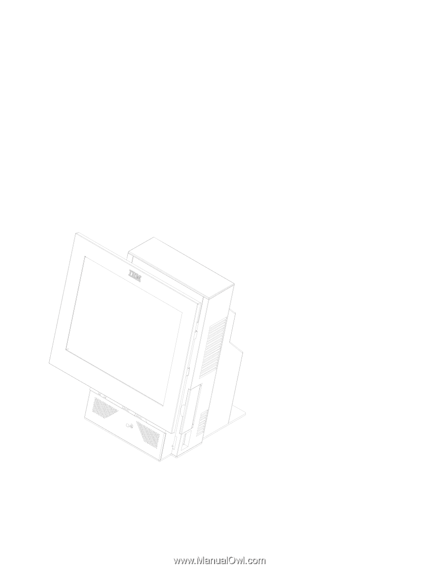
IBM SurePOS 500 Series Models 533, 543, 544, 553, 563, 564, 573, and 5A3 enable you to provide fast, accurate customer service and to manage your restaurant or store efficiently. The machine type for these models is 4840. You can configure the SurePOS 500 Models 5x3 and 544/564 systems to support - IBM 4840-544 | Service Guide - Page 28
Introduction August 3, 2006 Figure 1. SurePOS 500 Models 5x3 and 544/564 configuration with optional features SurePOS 500 Models 5x3 and 544/564 All SurePOS 500 Models 5x3 and 544/564 (except Model 5A3) use an Intel® Celeron®, 2.0-GHz processor. The Model 5A3 uses an Intel Pentium® 4, 2.8-GHz - IBM 4840-544 | Service Guide - Page 29
Windows® XP Embedded | for Point of Service. | 2. Wx3 models are preloaded with Microsoft Windows XP Professional. | Table 1. SurePOS 500 Models 5x3 and 544/564 Features | ||| Model Operator terminal Audio | ||| 533/W33 12.1-in. single-bulb No ||| 543/E43/W43 12.1-in. dual-bulb No - IBM 4840-544 | Service Guide - Page 30
Exactly two memory slots are present. Two supported DIMMs can be use in any combination. v IBM 1.44-MB, external diskette drive v Three-track MSR v Dual-sided, single-track MSR (Japan and Korea only) v Mouse and keyboard "Y" cable v IBM SurePOS 500/600 Series Compact ANPOS Keyboard v 4610 SureMark - IBM 4840-544 | Service Guide - Page 31
and Power Interface (ACPI)1 v Flash-update utility program | v SurePOS 500 Models 5x3 and 544/564 Diagnostic programs v Device drivers 1. ACPI is supported only on Windows-based systems Chapter 1. Introducing the IBM SurePOS 500 Series Models 533, 543, 544, 553, 563, 564, 573, and 5A3 5 - IBM 4840-544 | Service Guide - Page 32
tray) v Secured to a full-size cash drawer (with an integration tray) v Secured to a wall. The Wall Mount feature must be specified when ordering your SurePOS 500 Models 5x3 and 544/564. v Using a mounting foot for the cash drawer or mounting a 4820 SurePoint Solution without integration tray - IBM 4840-544 | Service Guide - Page 33
you are using a countertop integration tray, the base foot on the SurePOS 500 Models 5x3 and 544/564 is replaced with a mounting bracket. The unit is then securely attached to the integration tray with two screws. Figure 3 shows a SurePOS 500 Models 5x3 and 544/564 and an IBM 4610 SureMark printer - IBM 4840-544 | Service Guide - Page 34
System mounting options August 3, 2006 Figure 4 shows a SurePOS 500 Models 5x3 and 544/564, a keyboard and a IBM 4610 SureMark printer mounted to a countertop keyboard-integration tray. Figure 4. Countertop mounting option with keyboard-integration tray 8 - IBM 4840-544 | Service Guide - Page 35
distributed character display and IBM 4820 SurePoint® Solution display option. Figure 5. Cash-drawer mounting option with keyboard integration tray, integrated character display and 4820 SurePoint Solution options Chapter 1. Introducing the IBM SurePOS 500 Series Models 533, 543, 544, 553, 563, 564 - IBM 4840-544 | Service Guide - Page 36
System mounting options August 3, 2006 Figure 6 shows the compact-size cash-drawer with the keyboard-integration tray mounting option. Figure 6. Compact-size cash-drawer with keyboard-integration tray mounting option 10 - IBM 4840-544 | Service Guide - Page 37
August 3, 2006 Wall mounting Wall-mounting option Figure 7 illustrates the SurePOS 500 Models 5x3 and 544/564 with the Wall Mount option. Figure 7. Wall mounting option Chapter 1. Introducing the IBM SurePOS 500 Series Models 533, 543, 544, 553, 563, 564, 573, and 5A3 11 - IBM 4840-544 | Service Guide - Page 38
optional mounting foot. You must specify this feature when ordering your SurePOS 500 Models 5x3 and 544/564. This option allows you to integrate a 4820 SurePoint Solution without a integration tray or to mount your 4840 on a cash drawer. Note: Use of the mounting foot with Model 573 on a narrow cash - IBM 4840-544 | Service Guide - Page 39
August 3, 2006 Display mounting option Figure 9. Remote display tablet mounting option Chapter 1. Introducing the IBM SurePOS 500 Series Models 533, 543, 544, 553, 563, 564, 573, and 5A3 13 - IBM 4840-544 | Service Guide - Page 40
the network. The following functions are supported: v Selectable startup sequence v Update POST/BIOS from the network v Ethernet setup v Power up (wake) on LAN Compatible products IBM designed the SurePOS 500 Models 5x3 and 544/564 to operate with the many POS PC applications. These applications are - IBM 4840-544 | Service Guide - Page 41
IBM-supplied driver for Windows that must be installed in order to use used in the configurations for keyboard and mouse. Table 4. PS/2 keyboard/mouse port assignment Port assignment Addresses IRQ level IBM PS/2 keyboard 60 and 64 1 Mouse 60 and 64 12 The SurePOS 500 Models 5x3 and 544 - IBM 4840-544 | Service Guide - Page 42
System management August 3, 2006 Machine serial number location The serial number and model number are located on the right front. See A in Figure 10. B points to the tablet size label. A B Figure 10. Serial number location: A 16 - IBM 4840-544 | Service Guide - Page 43
Utility 19 Using the Main using the Setup Utility and updating the flash BIOS. How to use the touch screen Before you use only as hard as necessary for use. Table 5. Using the touch screen Touch mode that a button was pressed and released. Not supported. Touch twice in quick Touch the object - IBM 4840-544 | Service Guide - Page 44
program. Other features of the program are: v Navigate the program and select items by using the keyboard or the touch screen. v Change information that is located within the square brackets the Setup Utility. This information is required during service. v Save your settings before exiting. 18 - IBM 4840-544 | Service Guide - Page 45
Press Del during POST when prompted, or tap the touch screen two times. Use the keys listed in the legend bar at the bottom of the screen to menu displays the online help information for the currently selected item.. You can use either a keyboard or the touch screen to make selections. Figure 12 is - IBM 4840-544 | Service Guide - Page 46
Control procedures August 3, 2006 Standard CMOS features This menu provides basic functions, like setting the time and date. It also provides basic information, such as BIOS version, Ethernet MAC address, memory size, and machine serial number. Advanced BIOS Features The Advanced BIOS window (see - IBM 4840-544 | Service Guide - Page 47
you can configure I/O devices, such as serial ports, Ethernet, parallel port, USB controller, and keyboard. Power Management Use the Power Management window to configure the power savings, hard disk time-out, video time-out, and other power settings. See Figure 14. Figure 14. Example of the Power - IBM 4840-544 | Service Guide - Page 48
SurePOS 500 Models 5x3 and 544/564: 1. Insert a formatted diskette into the diskette drive of a PC with Internet access. 2. Access the IBM Retail Store Solutions Web site at: www.ibm.com/solutions/ retail/store/. 3. Select Support on the left side of the panel, then select IBM SurePOS 500 in use. - IBM 4840-544 | Service Guide - Page 49
August 3, 2006 Control procedures Clearing the CMOS settings The SurePOS 500 Models 5x3 and 544/564 uses battery-backed CMOS memory to store system settings. If the CMOS memory becomes corrupted and the system does not boot, you can restore the factory - IBM 4840-544 | Service Guide - Page 50
Control procedures August 3, 2006 24 - IBM 4840-544 | Service Guide - Page 51
(for the 5x3 models 31 | Using the IBM Diagnostics for POS System Units and Peripherals (for the | 5x4 models 31 | Diagnostic wrap plugs 31 This chapter contains the problem determination procedures for the SurePOS 500 Models 5x3 and 544/564 and peripheral I/O devices. A software - IBM 4840-544 | Service Guide - Page 52
, continue problem resolution at "Troubleshooting" on page 27. Notes: | 1. For internal options and peripheral devices, you can use the diagnostic | programs to help resolve problems. Refer to "Running Diagnostics" on page 30. 2. Some devices that attach to the system have test instructions - IBM 4840-544 | Service Guide - Page 53
August 3, 2006 Troubleshooting Troubleshooting If the SurePOS 500 Models 5x3 and 544/564 system fails and there is no error message or beep code, see Table 7 to find problem symptoms and take the related action. Note: Corrupted CMOS may cause unpredictable problems. Before exchanging the system - IBM 4840-544 | Service Guide - Page 54
Troubleshooting drawer not opening 1. Run the Setup Utility to make sure that IBM cash drawer setting is enabled. 2. Ensure that the cash drawer cable For example, the test 2. Replace the latch and the sensor assembly card. See "Removing and replacing the latch and sensor assembly" on page - IBM 4840-544 | Service Guide - Page 55
Troubleshooting lit. 1. Adjust the brightness using the button located on the on page 30. 3. Reinstall touch driver. 4. Replace the operator display 4. Replace the LED board. See "LED card and cable - removing and replacing" on page problem solving. 1. See Chapter 5, "Compact ANPOS Keyboard," on - IBM 4840-544 | Service Guide - Page 56
the Service Diskette code from the IBM Retail Store Solutions | Web site using the following steps: | 1. Go to www.ibm.com/solutions/retail/store/ and select Support. | 2. Under SurePOS 500/600 Series select SurePOS 500-xx3 Downloads. | 3. Select SurePOS 500-xx3 Diagnostic/Service Diskette - IBM 4840-544 | Service Guide - Page 57
the diagnostics: | 1. Go to www.ibm.com/solutions/retail/store/ and select Support. | 2. Under SurePOS 500/600 Series select SurePOS 500-xx3 Downloads. | 3. Select IBM Diagnostics for POS Systems and Peripherals | Using the IBM Diagnostics for POS System Units and Peripherals (for | the - IBM 4840-544 | Service Guide - Page 58
Troubleshooting v pin 6 diode 1N4149 -| - IBM 4840-544 | Service Guide - Page 59
fan - removing and replacing 52 LED card and cable - removing and replacing 53 Calibrating replacing 58 Connecting the cables and using cable-ties for counter mount systems rear connector panel 59 Dual-video adapter - removing and replacing SurePOS 500 Models 5x3 and 544/ IBM Corp. 2004, 2006 33 - IBM 4840-544 | Service Guide - Page 60
blank lock insert 116 Distributed customer display - disassembling 118 IBM 4610 SureMark printers - removing and replacing 121 4610 contains the FRU removal and replacement procedures for all SurePOS 500 Models 5x3 and 544/564 models (4840), although some procedures are for features that are - IBM 4840-544 | Service Guide - Page 61
. v Take additional care when handling devices during cold weather because heating reduces indoor humidity and increases static electricity. Chapter 4. Removing and replacing FRUs for the SurePOS 500 Models 5x3 and 544/564 35 - IBM 4840-544 | Service Guide - Page 62
Covers August 3, 2006 Covers - removing and replacing This section contains remove and replace procedures for the covers. HDD cover and speaker panel - removing and replacing 1. Tilt the top of the display tablet back. 2. On one side, insert a paper clip to release the tab A , and pull the HDD - IBM 4840-544 | Service Guide - Page 63
August 3, 2006 Covers HDD cover clips - removing and replacing 1. Switch OFF the power to the SurePOS 500 Models 5x3 and 544/564. Unplug the power cord from the external power source. 2. Remove the HDD cover. See "HDD cover and speaker panel - removing and replacing" on page - IBM 4840-544 | Service Guide - Page 64
Covers August 3, 2006 Rear cover - removing and replacing 1. Switch OFF the power to the SurePOS 500 Models 5x3 and 544/564. Unplug the power cord from the external power source. 2. Facing the rear of the system, press in on both sides A , and lift upward B , as - IBM 4840-544 | Service Guide - Page 65
August 3, 2006 Covers Figure 19. Removing rear cover Chapter 4. Removing and replacing FRUs for the SurePOS 500 Models 5x3 and 544/564 39 - IBM 4840-544 | Service Guide - Page 66
- removing and replacing 1. Remove the rear cover, following the procedure in "Rear cover - removing and replacing" on page 38. 2. Facing the rear of the system, use a screwdriver to lift the tab A while pulling the top cover toward the rear. See Figure 21 on page 41 and Figure 20. 3. Repeat for the - IBM 4840-544 | Service Guide - Page 67
August 3, 2006 Covers B Figure 21. Releasing top cover Chapter 4. Removing and replacing FRUs for the SurePOS 500 Models 5x3 and 544/564 41 - IBM 4840-544 | Service Guide - Page 68
- removing and replacing" on page 40. 4. Remove the center cover "Tower center cover - removing and replacing" on page 45. 5. From the front of the system, use a flat-bladed screwdriver to pry open four latches on the front of each side cover A , as shown in Figure 22. 6. Pull the side cover toward - IBM 4840-544 | Service Guide - Page 69
door from the hinge by pressing the two wire pieces as shown in Figure 24 on page 44. Chapter 4. Removing and replacing FRUs for the SurePOS 500 Models 5x3 and 544/564 43 - IBM 4840-544 | Service Guide - Page 70
Covers August 3, 2006 Figure 24. Removing side panel door only To remove the hinge, remove the right side cover. See "Side covers - removing and replacing" on page 42. To replace, reverse the removal procedure. 44 - IBM 4840-544 | Service Guide - Page 71
- removing and replacing" on page 46. Figure 25. Removing tower center cover To replace, reverse the removal procedure. Chapter 4. Removing and replacing FRUs for the SurePOS 500 Models 5x3 and 544/564 45 - IBM 4840-544 | Service Guide - Page 72
Covers August 3, 2006 Hinge cover - removing and replacing 1. Remove the tablet. See "Display tablet - removing and replacing" on page 48. 2. Remove the HDD cover. See "HDD cover and speaker panel - removing and replacing" on page 36. 3. Pull out at the bottom of the hinge cover where the tabs - IBM 4840-544 | Service Guide - Page 73
August 3, 2006 MSR Magnetic stripe reader (MSR) - removing and replacing 1. Switch OFF the power to the SurePOS 500 Models 5x3 and 544/564. Unplug the power cord from the external power source. 2. Unplug the MSR cable A , as shown in Figure 27 and remove the cable from the - IBM 4840-544 | Service Guide - Page 74
tablet - removing and replacing Refer to Figure 28 on this page and Figure 29 on page 49. 1. Switch OFF the power to the SurePOS 500 Models 5x3 and 544/564. Unplug the power cord from the external power source. 2. Tilt the tablet back and loosen the thumbscrew A under the tablet. 3. Disconnect the - IBM 4840-544 | Service Guide - Page 75
Remove the LED card. See "LED card and cable - removing and replacing" on page 53. 7. Disconnect the cable clamps behind the LED card and under the tablet guide in the frame. To replace, reverse this procedure. Chapter 4. Removing and replacing FRUs for the SurePOS 500 Models 5x3 and 544/564 49 - IBM 4840-544 | Service Guide - Page 76
Hinge assembly August 3, 2006 Hinge assembly - removing and replacing 1. Switch OFF the power to the SurePOS 500 Models 5x3 and 544/564. Unplug the power cord from the external power source. 2. Remove the tablet. See "Display tablet - removing and replacing" on page 48. 3. Remove the HDD - IBM 4840-544 | Service Guide - Page 77
Attention: The HDD is a static-sensitive device. See "Handling static-sensitive devices" on page 34. 1. Switch OFF the power to the SurePOS 500 Models 5x3 and 544/564. Unplug the power cord from the external power source. 2. Tilt back the tablet. 3. Remove the front cover as described at "HDD - IBM 4840-544 | Service Guide - Page 78
August 3, 2006 8. Power ON the system and use the Setup Utility to verify that the system recognizes of the HDD. HDD cables - removing and replacing 1. Switch OFF the power to the SurePOS 500 Models 5x3 and 544/564. Unplug the power cord from the external power source. See Figure 31 on page 51 - IBM 4840-544 | Service Guide - Page 79
make sure you replace with the correct part number. On some models, the LED card includes a presence sensor. 1. Switch OFF the power to the SurePOS 500 Models 5x3 and 544/564. Unplug the power cord from the external power source. 2. Remove the front cover as described at "HDD cover and speaker panel - IBM 4840-544 | Service Guide - Page 80
LED card and cable August 3, 2006 Calibrating the presence sensor (Models 563, 564, 573, and 5A3 only) A presence sensor A Figure 33 causes the system to resume from - IBM 4840-544 | Service Guide - Page 81
Speaker - removing and replacing Refer to Figure 34 on this page and Figure 35 on page 56. 1. Switch OFF the power to the SurePOS 500 Models 5x3 and 544/564. Unplug the power cord from the external power source. 2. Remove the front cover as described at "HDD cover and speaker panel - removing - IBM 4840-544 | Service Guide - Page 82
Speaker Figure 35. Speaker hooks August 3, 2006 Figure 36. Keyhole slots for speaker hooks 56 - IBM 4840-544 | Service Guide - Page 83
running when the system is connected to power, but has been powered Off. This is normal operation. 1. Switch OFF the power to the SurePOS 500 Models 5x3 and 544/564. Unplug the power cord from the external power source. 2. Remove the back cover as described at "Rear cover - removing and replacing - IBM 4840-544 | Service Guide - Page 84
Cable tie bar August 3, 2006 Cable tie bar - removing and replacing 1. Switch OFF the power to the SurePOS 500 Models 5x3 and 544/564. 2. Unplug the power cord from the external power source. 3. Remove the rear cover as shown at "Rear cover - removing and replacing" on page 38. 4. - IBM 4840-544 | Service Guide - Page 85
explains how to connect cables to the rear connector panel (shown in Figure 40 on page 60). Use cable ties if desired. Connect the cables in the lowest row first, then work upwards connecting any additional cables. Chapter 4. Removing and replacing FRUs for the SurePOS 500 Models 5x3 and 544/564 59 - IBM 4840-544 | Service Guide - Page 86
on page 61. A B C D E F G H I J Figure 40. Rear connector panel Ref. Connector A Serial connectors (3) B Parallel connector C External video connector D Ethernet connector E USB connectors (2) F 12-volt USB connector G 24-volt USB connector H Distributed customer display - IBM 4840-544 | Service Guide - Page 87
. 5. For cables routed under the counter, install a cable-tie around all rear connector panel cables exiting through the hole. Allow sufficient length for cleaning and servicing. Chapter 4. Removing and replacing FRUs for the SurePOS 500 Models 5x3 and 544/564 61 - IBM 4840-544 | Service Guide - Page 88
adapter - removing and replacing The dual-video card is optional on all models of 4840. Attention: The dual-video adapter is a static-sensitive device. See "Handling static-sensitive devices" on page 34. 1. Switch OFF the power to the SurePOS 500 Models 5x3 and 544/564. Unplug the power cord from - IBM 4840-544 | Service Guide - Page 89
August 3, 2006 Dual-video adapter B A E JP32-35 JP29-31 D C JP7 Figure 43. Dual video adapter jumper location To replace the video card, reverse this procedure. Chapter 4. Removing and replacing FRUs for the SurePOS 500 Models 5x3 and 544/564 63 - IBM 4840-544 | Service Guide - Page 90
Cooling duct August 3, 2006 Cooling duct - removing and replacing 1. Switch OFF the power to the SurePOS 500 Models 5x3 and 544/564. Unplug the power cord from the external power source. 2. Remove the back cover as described at "Rear cover - removing and replacing" on page 38. 3. - IBM 4840-544 | Service Guide - Page 91
"Processor module - removing and replacing" on page 71. v Dual video adapter, if installed. See "Dual-video adapter - removing and replacing" on page 62. Remove jumpers JP29-JP35 (VPD). a. Boot the service diskette. Chapter 4. Removing and replacing FRUs for the SurePOS 500 Models 5x3 and 544/564 65 - IBM 4840-544 | Service Guide - Page 92
System board b. Choose POS System Test. c. Choose Utilities. d. Choose Vital Product Data Utility. e. Choose Update VPD. f. Choose the model and press Enter. g. Choose Update VPD again. h. Enter the machine - IBM 4840-544 | Service Guide - Page 93
the jumper on pins 2-3 JP29-JP35 pins 1-2 Dual video adapter - to install the dual video adapter, remove all jumpers from these pins JP6 pins 1-2 - removing and replacing 1. Switch OFF the power to the SurePOS 500 Models 5x3 and 544/564. Unplug the power cord from the external power source. - IBM 4840-544 | Service Guide - Page 94
and replacing" on page 76. 6. Remove the old battery from the slot A as shown in Figure 47. B A E JP32-35 JP29-31 D C JP7 Figure 47. Dual video adapter or jumper location 7. Insert the new battery with the positive side to the left, as you face the back of the machine. Reverse the - IBM 4840-544 | Service Guide - Page 95
system board while still attached to the fansink, you must carefully remove it. Use the following steps to replace the fansink. Refer to Figure 48 on page 70. 1. Switch OFF the power to the SurePOS 500 Models 5x3 and 544/564. Unplug the power cord from the external power source. 2. Remove the back - IBM 4840-544 | Service Guide - Page 96
Fansink August 3, 2006 Figure 48. Removing the fansink 70 - IBM 4840-544 | Service Guide - Page 97
new processor and fansink come as one FRU. Do not use the old fansink when replacing the processor. Attention: Establish personal loosen the heatsink thermal material. 2. Switch OFF the power to the SurePOS 500 Models 5x3 and 544/564. Unplug the power cord from the external power source. 3. Remove - IBM 4840-544 | Service Guide - Page 98
of memory modules into either socket and in any combination of sizes. Figure 49. Memory socket location 1. Switch OFF the power to the SurePOS 500 Models 5x3 and 544/564. Unplug the power cord from the external power source. 2. Remove the back cover. See "Covers - removing and replacing" on page 36 - IBM 4840-544 | Service Guide - Page 99
fully upright and engaged in the memory module side notches. 8. Replace the components removed earlier in this procedure. Chapter 4. Removing and replacing FRUs for the SurePOS 500 Models 5x3 and 544/564 73 - IBM 4840-544 | Service Guide - Page 100
page 75. 3. Remove the two screws securing the EMC shield. Figure 51. Removing the PC card adapter slot blank PC card - removing and replacing 1. Switch OFF the power to the SurePOS 500 Models 5x3 and 544/564. Unplug the power cord from the external power source. 2. Remove the HDD cover. See "HDD - IBM 4840-544 | Service Guide - Page 101
Setup Utility main menu at "The Setup Utility" on page 18. Note: Before removing a PC card with the system unit running Windows, IBM recommends that you stop the PC card in Windows before you physically remove it. Chapter 4. Removing and replacing FRUs for the SurePOS 500 Models 5x3 and 544/564 75 - IBM 4840-544 | Service Guide - Page 102
Rear connector panel (tailgate) August 3, 2006 Rear connector panel (tailgate) - removing and replacing 1. Switch OFF the power to the SurePOS 500 Models 5x3 and 544/564. Unplug the power cord from the external power source. 2. Remove the rear cover as described at "Covers - removing and replacing - IBM 4840-544 | Service Guide - Page 103
video connector D Ethernet connector E 12-volt USB connector F 24-volt USB connector G USB connectors (2) H Integrated or distributed customer display connector I Keyboard/mouse cable J Cash drawer connectors (2) Chapter 4. Removing and replacing FRUs for the SurePOS 500 Models - IBM 4840-544 | Service Guide - Page 104
Rear inner metal cover August 3, 2006 Rear inner metal cover - removing and replacing 1. Switch OFF the power to the SurePOS 500 Models 5x3 and 544/564. Unplug the power cord from the external power source. 2. Remove the back cover as described at "Covers - removing and replacing" on page 36. 3. - IBM 4840-544 | Service Guide - Page 105
of the system board. 7. Replace the rear inner metal cover and the rear cover. Figure 56. Integrated display Chapter 4. Removing and replacing FRUs for the SurePOS 500 Models 5x3 and 544/564 79 - IBM 4840-544 | Service Guide - Page 106
August 3, 2006 Base plate - removing and replacing Note: The base plate is not present when a mounting foot is used. 1. Switch OFF the power to the SurePOS 500 Models 5x3 and 544/564. Unplug the power cord from the external power source. 2. Remove the back cover as described at "Covers - removing - IBM 4840-544 | Service Guide - Page 107
80. The mounting foot is not present when a base plate is used. The mounting foot allows use of a 4820 SurePoint Solution without an integration tray or to sit on a cash drawer. To remove and replace the SurePOS 500 Models 5x3 and 544/564 attached to a mounting foot: 1. Remove the rear cover. See - IBM 4840-544 | Service Guide - Page 108
-standing SurePOS 500 Models 5x3 and 544/564 - removing from the base." v A mounting foot is available as a kit. The kit includes a metal foot and a plastic cable cover. The cable cover is for use with an integrated 4820 SurePoint Solution or the mounting foot can be used - IBM 4840-544 | Service Guide - Page 109
tie bar. See "Cable tie bar - removing and replacing" on page 58. 6. Remove the screws securing the unit to the base. 7. Lift the SurePOS 500 Models 5x3 and 544/564 off of the base. To replace a free standing system, reverse this procedure. Note: Secure the cables to the cable tie bar with tie - IBM 4840-544 | Service Guide - Page 110
. Unplug the system power cord from the external power source. 2. If the SurePOS 500 Models 5x3 and 544/564 is attached to a countertop by means of an integration tray, go to step 3. If the system is mounted directly on a countertop using the base foot of the system unit: a. Remove the rear cover as - IBM 4840-544 | Service Guide - Page 111
the cable tie bar (see "Cable tie bar - removing and replacing" on page 58. A C B Figure 61. Removing the base foot from the SurePOS 500 Models 5x3 and 544/564 3. If the system is attached to a countertop by means of an integration tray: a. Remove the narrow filler panel F between the system and - IBM 4840-544 | Service Guide - Page 112
panel has a slot underneath to allow cables to be routed out the back. b. After installing the outer ends of filler panels B into the integration tray, use the narrow filler panel A to lock the filler panels together between the system and the printer. 86 - IBM 4840-544 | Service Guide - Page 113
configuration used, there may be unused filler panels. 5. Plug the system and printer AC power cords into an AC outlet. 6. After your installation is complete, press the printer power switch under the printer cover to power on the printer. Chapter 4. Removing and replacing FRUs for the SurePOS 500 - IBM 4840-544 | Service Guide - Page 114
drawer with a non-keyboard integration tray. Figure 64. Cash drawer mounted with a non-keyboard integration tray for the SurePOS 500 Models 5x3 and 544/564 The SurePOS 500 Models 5x3 and 544/564 mounts to a cash drawer by means of an adapter plate, which attaches to an integration tray secured to - IBM 4840-544 | Service Guide - Page 115
cables from the front and rear connector panels and unplug the line cord from the power supply. 7. Remove the thumbscrews (2) securing the SurePOS 500 Models 5x3 and 544/564 adapter plate A to the integration tray, as shown in Figure 66 on page 90. Then slide the system and adapter plate to - IBM 4840-544 | Service Guide - Page 116
Non-keyboard cash drawer mount August 3, 2006 B C A Figure 66. Detaching system from cash drawer integration tray 8. Remove printer B from the printer base mounting plate C by sliding it off the two mounting plate tabs. To replace a system on a cash drawer non-keyboard integration tray, reverse - IBM 4840-544 | Service Guide - Page 117
removed and mounted the same way - when the full-size keyboard-integration tray is used for a countertop or cash drawer mount. Therefore, the instructions for the countertop and cash drawer mount have been combined. Chapter 4. Removing and replacing FRUs for the SurePOS 500 Models 5x3 and 544/564 91 - IBM 4840-544 | Service Guide - Page 118
August 3, 2006 The following procedures tell you how to remove the different devices on the full-size keyboard-integration tray: 1. Prepare the SurePOS 500 Models 5x3 and 544/564 for disassembly by performing the necessary steps for the devices that are being removed: a. Switch OFF the power to the - IBM 4840-544 | Service Guide - Page 119
view in Figure 69. A B Figure 69. Removing the keyboard Y-cable b. Disconnect the Y-cable A from the keyboard/mouse connector located on the front-underside of the SurePOS 500 Models 5x3 and 544/564. Chapter 4. Removing and replacing FRUs for the - IBM 4840-544 | Service Guide - Page 120
Note: See the 4610 SureMark Point-of-Sale Printers User's Guide for detailed information about printer switch settings and cabling. C TG4 and TG5 printers a. Unplug the 4610 SureMark printer cable from the SurePOS 500 Models 5x3 and 544/564 rear connector panel, as show in Figure 40 on page 60. - IBM 4840-544 | Service Guide - Page 121
the 4820 display cable A from the 4820 connector located on the back of the display, and from the rear connector panel on the SurePOS 500 Models 5x3 and 544/564. Remove cable. c. Remove the 4820 by removing the four screws G from the display mounting bracket B . Carefully place the 4820 display on - IBM 4840-544 | Service Guide - Page 122
564 from the keyboard integration tray, see Figure 72 for callout locations and perform the following steps: A B C Figure 72. Removing the SurePOS 500 Models 5x3 and 544/564 from the integration tray a. Loosen the thumbscrew on the cable tie bar and swing the cable tie bar out of the way. b. Loosen - IBM 4840-544 | Service Guide - Page 123
and then back so the three tabs B are free from the three tab holes C on the cash drawer. Chapter 4. Removing and replacing FRUs for the SurePOS 500 Models 5x3 and 544/564 97 - IBM 4840-544 | Service Guide - Page 124
can not be placed on the compact-size keyboard-integration tray. Figure 74. Compact cash drawer with keyboard-integration tray 1. Prepare the SurePOS 500 Models 5x3 and 544/564 for disassembly by performing the necessary steps for the devices that are being removed: a. Switch OFF the power to the - IBM 4840-544 | Service Guide - Page 125
tray 2. To remove the distributed customer display, perform the following steps: a. Unplug the distributed character display cable F from the SurePOS 500 Models 5x3 and 544/564 rear connector panel, as show in Figure 40 on page 60. b. Unroute the distributed character display cable F to enable - IBM 4840-544 | Service Guide - Page 126
the keyboard cable B from the Y-cable C . 4. To remove the keyboard Y-cable, perform the following steps: a. Unplug the Y-cable C from the SurePOS 500 Models 5x3 and 544/564 front connector panel keyboard/mouse connector, as show in Figure 76. See "Connecting cables to the side access panel" on page - IBM 4840-544 | Service Guide - Page 127
place. b. Disconnect the 4820 display cable A from the 4820 connector located on the back of the display, and from the rear connector panel on the SurePOS 500 Models 5x3 and 544/564. Remove the cable. Chapter 4. Removing and replacing FRUs for the - IBM 4840-544 | Service Guide - Page 128
Compact-size keyboard integration tray August 3, 2006 c. Remove the 4820 display by removing the two screws C from the display mounting bracket B , as shown in Figure 77 on page 101. Carefully place the 4820 display on a smooth, clean surface. Figure 78. Removing the 4820 SurePoint Solution from - IBM 4840-544 | Service Guide - Page 129
/564 from the keyboard integration tray, see Figure 79 for callout locations and perform the following steps: A B Figure 79. Removing the SurePOS 500 Models 5x3 and 544/564 from the integration tray a. Loosen the thumbscrew on the cable tie bar, if present, and rotate the cable tie bar out of the - IBM 4840-544 | Service Guide - Page 130
Compact-size keyboard integration tray August 3, 2006 d. Slide the SurePOS 500 Models 5x3 and 544/564 forward to unlatch it from the base brackets and lift up to remove. Carefully place the SurePOS 500 Models 5x3 and 544/564 on a smooth, clean surface. 7. To remove the keyboard integration tray on - IBM 4840-544 | Service Guide - Page 131
cash drawer: 1. If the cash drawer is mounted to the underside of a counter, refer to the instructions that came with the mounting brackets. 2. Switch OFF the power to the SurePOS 500 Models 5x3 and 544/564. Unplug the system power cord from the external power source. 3. Open the cash-drawer rear - IBM 4840-544 | Service Guide - Page 132
August 3, 2006 Rail Button (one on each side) Drawer Guide Figure 81. Removing and replacing a full size cash drawer To way out. 3. Position the rear of the drawer into the slides so that the drawer guide on each side of the drawer aligns with the corresponding opening on each side, as shown - IBM 4840-544 | Service Guide - Page 133
into the base. 3. Reinstall the latch assembly. 4. Reinstall the top cover if it was removed. 5. Reinstall the drawer. Chapter 4. Removing and replacing FRUs for the SurePOS 500 Models 5x3 and 544/564 107 - IBM 4840-544 | Service Guide - Page 134
: 1. Disconnect the cash drawer cable. 2. Open the cash drawer and pull it all the way out. 3. Remove the till. 4. Facing the front of the drawer, use a coin or large screwdriver to move the drawer slide latches to the right until the drawer is released from the slide assembly (see Figure 83 - IBM 4840-544 | Service Guide - Page 135
secure the slide to the base and lift the slide assembly out. See Figure 86 on page 110. Chapter 4. Removing and replacing FRUs for the SurePOS 500 Models 5x3 and 544/564 109 - IBM 4840-544 | Service Guide - Page 136
Cash drawer FRUs August 3, 2006 Screws Slide assembly Figure 86. Compact cash drawer slide assembly To replace the slide assembly: 1. To replace the slide assembly, place the slide assembly into the base so that the screw holes are aligned. 2. Insert and tighten the screws that secure the slide to - IBM 4840-544 | Service Guide - Page 137
shaft, gently pry the roller and shaft out. Snap the new set into position. Be sure to use the ball-bearing rollers on the base and the plastic rollers on the drawer. Removing and replacing the 88 on page 112). Chapter 4. Removing and replacing FRUs for the SurePOS 500 Models 5x3 and 544/564 111 - IBM 4840-544 | Service Guide - Page 138
Cash drawer FRUs August 3, 2006 Coin roll cutter Cutter latches Figure 88. Removing the coin-roll cutter 4. To replace the cutter, snap the new cutter into position from the outside. 5. Reassemble. Removing and replacing the security clip To remove the security clip: 1. Disconnect the cash-drawer - IBM 4840-544 | Service Guide - Page 139
out of the front of the drawer. Note: It might require some force to free the keylock assembly. Chapter 4. Removing and replacing FRUs for the SurePOS 500 Models 5x3 and 544/564 113 - IBM 4840-544 | Service Guide - Page 140
Common cash drawer FRUs Lock Actuator Rod Lock Retainer Clip August 3, 2006 Figure 91. Keylock assembly To replace the keylock assembly: 1. Ensure that the lock actuator rod is in the position shown in Figure 91. 2. Slide the lock assembly all the way into the opening in the front of the drawer, - IBM 4840-544 | Service Guide - Page 141
drawer FRUs Pawl Latches Latch Plate Bracket Cam Latches Pawl Screws Card Assembly Cam Cam Spring Figure 92. Cash-drawer latch and retain the card assembly and remove the card assembly (see Figure 92). Chapter 4. Removing and replacing FRUs for the SurePOS 500 Models 5x3 and 544/564 115 - IBM 4840-544 | Service Guide - Page 142
lock insert fully into the lock cylinder. 5. While holding the lock insert in place with your finger, remove the installation-removal key. 6. Test the lock using the keys that came with the insert to be sure that the lock operates correctly. Removing and replacing the blank lock insert To remove the - IBM 4840-544 | Service Guide - Page 143
of the lock cylinder. 5. Use the blank lock-insert handle to turn the locking screw clockwise until it reaches the bottom of the hole. Do not overtighten. To replace the blank lock insert, reverse this procedure. Chapter 4. Removing and replacing FRUs for the SurePOS 500 Models 5x3 and 544/564 117 - IBM 4840-544 | Service Guide - Page 144
a distributed customer display: 1. Gently spread the arms of the yoke open slightly and slide the display out of the yoke. You can use a small screwdriver if necessary. Figure 94. Distributed customer display 2. Unplug the display cable from the display. 3. Go to the appropriate non-keyboard - IBM 4840-544 | Service Guide - Page 145
the cash drawer, with 2 thumbscrews F and snap the entire unit into place at the rear of the tray. Chapter 4. Removing and replacing FRUs for the SurePOS 500 Models 5x3 and 544/564 119 - IBM 4840-544 | Service Guide - Page 146
Distributed customer display August 3, 2006 5. To install a distributed customer display on a keyboard integration tray, perform the following steps: a. Remove filler panel E and rear modesty panel G Figure 96. b. Route the character display cable through the hole behind mounting post B as show in - IBM 4840-544 | Service Guide - Page 147
Powered USB port C Not used on Models 5x3 D Cash drawer connector E RS-232 mode switch An RS-232 printer may be used with a power brick or a special cable may be use to draw power from the 24-V powered USB port. Chapter 4. Removing and replacing FRUs for the SurePOS 500 Models 5x3 and 544/564 121 - IBM 4840-544 | Service Guide - Page 148
4610 SureMark printer August 3, 2006 4610 SureMark - removal 1. Switch OFF the power at the SurePOS 500 Models 5x3 and 544/564. 2. Remove the SurePOS 500 Models 5x3 and 544/564 rear cover and filler panels (see "Rear cover - removing and replacing" on page 38). 3. Remove the power supply (see " - IBM 4840-544 | Service Guide - Page 149
Use the following instructions for replacing the 4610 SureMark printer: 1. Check the printer RS-232 mode switch settings, which is near the rear cable connections. See E in Figure 97 on page 121 for switch location. For switch settings, see the IBM 4610 SureMark Point-of-Sale Printers User's Guide - IBM 4840-544 | Service Guide - Page 150
4610 SureMark printer August 3, 2006 4610 SureMark printer installation on a non-keyboard integration tray Install the 4610 SureMark printer on the non-keyboard integration tray, by performing the following steps: 1. Attach the printer cables to the printer. 2. Attach the printer mounting plate to - IBM 4840-544 | Service Guide - Page 151
August 3, 2006 4610 SureMark printer A B Figure 101. 4610 SureMark printer cable routing on a non-keyboard integration tray Chapter 4. Removing and replacing FRUs for the SurePOS 500 Models 5x3 and 544/564 125 - IBM 4840-544 | Service Guide - Page 152
printer on the keyboard integration tray, by performing the following steps: Note: See the 4610 SureMark Point-of-Sale Printers User's Guide for detailed information about printer switch settings and cabling. C B A Figure 102. Installing the 4610 SureMark printer onto the keyboard integration - IBM 4840-544 | Service Guide - Page 153
devices can be connected to the SurePOS 500 Models 5x3 and 544/564 15-pin port. Distributed 4820 SurePoint Solution To remove a distributed 4820, follow the instructions provided in the IBM 4820 SurePoint Solution Installation and Service Guide and install the 4820 SurePoint Solution display - IBM 4840-544 | Service Guide - Page 154
G D A B Figure 103. 4820 SurePoint Solution installation 4. Disconnect the 4820 display cable from the external video connector on the 4820 and from the rear connector panel A of the SurePOS 500 Models 5x3 and 544/564, as shown in Figure 103. 5. See Figure 104 on page 129. Remove the 4820 base plate - IBM 4840-544 | Service Guide - Page 155
August 3, 2006 6. Reassemble in reverse order. A 4820 SurePoint Solution C D Figure 104. Removing the 4820 SurePoint Solution display from the base plate. Chapter 4. Removing and replacing FRUs for the SurePOS 500 Models 5x3 and 544/564 129 - IBM 4840-544 | Service Guide - Page 156
. Removing the 4820 SurePoint Solution cable and covers 4. Disconnect the 4820 display cable A from the external video connector on the 4820 and from the rear connector panel of the SurePOS 500 Models 5x3 and 544/564, as show in Figure 105. 5. Remove the 4820 display from the mounting bracket B by - IBM 4840-544 | Service Guide - Page 157
August 3, 2006 4820 SurePoint Solution 7. Remove the 4820 base plate B from the SurePOS 500 Models 5x3 and 544/564 base plate by removing the four screws C , as shown in Figure 106. tray, as shown in Figure 106. Chapter 4. Removing and replacing FRUs for the SurePOS 500 Models 5x3 and 544/564 131 - IBM 4840-544 | Service Guide - Page 158
the top front center of the base. 5. Snap plate F onto the back of the tablet. 6. Attach the tablet and plate assembly to the base E , using 4 screws D . 7. Reattach covers A and B . 8. See Figure 108 on page 133. Connect the tower end of the extension cable A , and the adapter B as shown. 9. Attach - IBM 4840-544 | Service Guide - Page 159
August 3, 2006 Figure 108. Tower end of remote display cable Chapter 4. Removing and replacing FRUs for the SurePOS 500 Models 5x3 and 544/564 133 - IBM 4840-544 | Service Guide - Page 160
August 3, 2006 134 - IBM 4840-544 | Service Guide - Page 161
using the CANPOS Keyboard Utility program. See the SurePOS 500/600 Installation and Operations Guide IBM representative. The part number for the caps is: 30R0037. Use Table 11 to determine the failing CANPOS keyboard FRU. Table 11. Repair actions for CANPOS keyboard problems keyboard logic card" on - IBM 4840-544 | Service Guide - Page 162
may respond sluggishly. The cursor calibrates itself as it is being used. If the problem persists, follow these steps: 1. Push the joystick to its Go into Microsoft WordPad or another word processor and swipe the MSR test card. Make sure data appears. 4. Ensure that the MSR cable are securely - IBM 4840-544 | Service Guide - Page 163
this style cap, replacement caps (part number 30R0037) can be purchased by calling 1-800-IBM-CALL (1-800-426-2255) in the U.S. and Canada. Customers outside the U.S. and Canada should contact their IBM representative. 2. FRUs for the keyboards listed in the following table are no longer available - IBM 4840-544 | Service Guide - Page 164
CANPOS keypad assembly You must remove the keyboard from the keyboard integration tray to service the keyboard. 1. To remove the keyboard from the keyboard integration tray, perform from the Y-cable C , if the Y-cable is used. 2. Replace the internal FRUs in the CANPOS keyboard keypad assembly: 138 - IBM 4840-544 | Service Guide - Page 165
August 3, 2006 CANPOS Keyboard a. Disconnect the cable from the rear of the keyboard. b. Remove the three screws from the underside of the front edge of the keyboard. c. Lift the front edge of the keyboard enough to access the cables inside the keyboard. Chapter 5. Compact ANPOS Keyboard 139 - IBM 4840-544 | Service Guide - Page 166
. See Figure 111 for cable callouts and locations. Keypad Assembly Ribbon Cable, to J3 Ribbon Cable, to J4 Keyboard Logic card J4 J3 Latch to J5 Ribbon Cable to MJ1 J5 J1 Ribbon Cable Connectors MJ1 Integrated Pointing Device Connector Figure 111. CANPOS keypad assembly without - IBM 4840-544 | Service Guide - Page 167
out of the keyboard base. See Figure 111 on page 140 for card and latch locations. To replace the logic card, reverse these steps. The CANPOS Keyboard Utility program can be used to download the information about the 32 programmable keys to the CANPOS keyboard. Chapter 5. Compact ANPOS Keyboard - IBM 4840-544 | Service Guide - Page 168
the two screws holding the MSR to the keypad assembly as shown in Figure 112. Lift the MSR up and off the the two plastic guides on the keypad assembly. Keypad Assembly MSR MSR control card to J2 MSR screws Ribbon Cable, to J3 Ribbon Cable, to J4 MSR connector Keyboard Logic - IBM 4840-544 | Service Guide - Page 169
pry the control card up and off the two plastic guides as shown in Figure 113. MSR Control Card MSR Reader A Figure 113. Removing the MSR control card To replace the MSR: 1. Install the MSR control card onto the keypad assembly by inserting the control card into the two plastic guide, as shown in - IBM 4840-544 | Service Guide - Page 170
August 3, 2006 144 - IBM 4840-544 | Service Guide - Page 171
shown . 146 . 148 . 150 . 152 . 154 156 . 158 . 160 . 162 . 164 This chapter contains part number information for the FRUs that are part of the SurePOS 500 Models 5x3 and 544/564. © Copyright IBM Corp. 2004, 2006 145 - IBM 4840-544 | Service Guide - Page 172
Assembly 1: (continued) Assembly 1: System parts 12 17 1 21 11 4 23 12 18 24 13 25 3 8 August 3, 2006 19 22 2 6 9 14 10 16 5 15 17 20 7 146 - IBM 4840-544 | Service Guide - Page 173
Models 533, 553) 1 Tablet - touch screen assembly, 12-inch, dual-bulb (Models 543, 544, 563, 564) 1 Tablet - touch screen assembly, 15-inch (Model 563, 564 shown) 1 Cover, tower, rear 1 Cover, side I/O 1 Blank kit, PC card System board see Assembly 2 1 HDD, 40 GB Fan, HDD with mounting bracket (all - IBM 4840-544 | Service Guide - Page 174
Assembly 2: System board 4 5 3 1 2 August 3, 2006 148 - IBM 4840-544 | Service Guide - Page 175
audio, no PC card (544 only) 1 Board, system, with audio, PC card (564 only) 1 Board, system, no audio, no PC card (5x3) 1 Board, system, with audio, PC card (5x3) 1 Memory, 1 GB 1 Fansink (with grease) 1 Retention kit, (not shown) 1 Battery 1 Card, Video (not shown) Appendix A. Parts catalog 149 - IBM 4840-544 | Service Guide - Page 176
Assembly 3: Wall Mount feature parts August 3, 2006 150 - IBM 4840-544 | Service Guide - Page 177
August 3, 2006 Asm- Index 3- -1 Part Number 14R0096 -2 14R0094 Assembly 3: (continued) Units Description Wall mount part numbers 1 Plate, wall mount (Note: Wall mount plate is the customer's responsibility to install) 1 Frame, wall mount Appendix A. Parts catalog 151 - IBM 4840-544 | Service Guide - Page 178
Assembly 4: Optional features 5 4 3 2 1 August 3, 2006 152 - IBM 4840-544 | Service Guide - Page 179
-2 -3 - -4 -5 Part Number 41D0151 39V5068 41D0152 39V5069 40N5755 06P5223 42M5864 14R0029 41D0149 Assembly 4: (continued) Units Description Optional features 1 MSR, three-track, (Models 5x3 and 544/564 except 573) 1 MSR, three-track, (Model 573 only) 1 MSR, dual sided single track, (Models 5x3 and - IBM 4840-544 | Service Guide - Page 180
August 3, 2006 Assembly 5: Countertop non-keyboard integration tray and filler panels 4 3 2 1 4 5 154 - IBM 4840-544 | Service Guide - Page 181
tray and filler panels 1 Plate and fence, countertop mount 1 Plate and fence, countertop mount, fits filler panel for non-printer use 1 Plate, printer mounting 1 Plate, terminal mounting (includes screws) 1 Panels, filler 1 Hardware, non-keyboard integration tray (kit - includes feet and screws - IBM 4840-544 | Service Guide - Page 182
August 3, 2006 Assembly 6: Cash drawer non-keyboard integration tray and filler panels 3 4 5 2 1 4 156 - IBM 4840-544 | Service Guide - Page 183
August 3, 2006 Asm- Index 6- -1 -2 -3 -4 -5 - - Part Number 41D0210 41D0211 41D0207 14R1998 20P0308 41D0212 41D0209 Assembly 6: (continued) Units Description Cash drawer non-keyboard integration tray and filler panels 1 Plate and fence, cash drawer mount 1 Plate, printer mounting 1 Plate, - IBM 4840-544 | Service Guide - Page 184
August 3, 2006 Assembly 7: Countertop and cash drawer keyboard integration tray and filler panels 5 4 2 2 5 4 3 6 3 3 3 3 2 2 1 1 158 - IBM 4840-544 | Service Guide - Page 185
August 3, 2006 Asm- Index 7- -1 - - - - - -2 - - - - -3 - - - - -4 - - - - -5 - - - -6 Part Number 41D0214 41D0208 14R0024 41D0215 14R0023 47P9273 41D0216 Assembly 7: (continued) Units Description Countertop and cash drawer keyboard integration tray and filler panels 1 FRU, plate/fence ASM, - IBM 4840-544 | Service Guide - Page 186
Assembly 8: 4820 mounting hardware and covers August 3, 2006 160 - IBM 4840-544 | Service Guide - Page 187
1 v Cover, outside 4820 mount 1 v Cover, inside 4820 mount 1 v M4x8 screws (not shown) (12) 1 v M4x10 screws (not shown) (4) 1 Cash drawer mounting foot assembly (Models 5x3 and 544/564) 1 v Base 1 v Cover Appendix A. Parts catalog 161 - IBM 4840-544 | Service Guide - Page 188
Assembly 9: Distributed mounting stand August 3, 2006 162 - IBM 4840-544 | Service Guide - Page 189
August 3, 2006 Asm- Index 9-1 -2 - Part Number 42J2692 57P4210 Assembly 9: (continued) Units Description Table top stand with covers Stand cover kit 1 Extension cable, tablet, with gender adapter (see Assembly 1, System parts) Appendix A. Parts catalog 163 - IBM 4840-544 | Service Guide - Page 190
Assembly 10: Tools (not shown) August 3, 2006 164 - IBM 4840-544 | Service Guide - Page 191
August 3, 2006 Assembly 10: (continued) Asm- Index 10- - - - Part Number 00G2380 72X8546 06P5223 Units Description Tools 1 Wrap plug, Ethernet (not illustrated) 1 Wrap plug, RS-232 and parallel port (not illustrated) 1 Diskette drive, external, USB For power cords see Appendix B, "Power Cords," - IBM 4840-544 | Service Guide - Page 192
August 3, 2006 166 - IBM 4840-544 | Service Guide - Page 193
, New Zealand Europe, Korea Denmark South Africa United Kingdom, Hong Kong Switzerland Chile, Italy Israel Japan United States United States, Chicago United States Brazil © Copyright IBM Corp. 2004, 2006 167 - IBM 4840-544 | Service Guide - Page 194
August 3, 2006 168 - IBM 4840-544 | Service Guide - Page 195
connector 180 Headphone connector 181 Serial connectors 181 Parallel connector 183 Diskette-drive connector 184 Ethernet connector 184 External video connector 185 Cash drawer connector (2 186 Integrated customer display connector 186 Temperature, humidity, and altitude limits 187 This - IBM 4840-544 | Service Guide - Page 196
described in Table 14 and Table 15. Table 14. SurePOS 500 Series dimensions Height (mm) Counter Counter Counter Wall Mount in. (311 mm) 12.60 in. (320 mm) 14.76 in. (375 mm) Table 15. SurePOS 500 Series weights Component Tower and 12-in. tablet Tower and 15-in. tablet Tower and 17-in. tablet - IBM 4840-544 | Service Guide - Page 197
August 3, 2006 Table 15. SurePOS 500 Series weights (continued) Component Weight Distributed APA display 0.73 kg (1.6 lbs) MSR (three-track or JUCC) 0.16 kg (0.41 lbs) Appendix C. System specifications and planning information 171 - IBM 4840-544 | Service Guide - Page 198
Dimensions of unit with 12-inch display 212mm August 3, 2006 321mm 379mm 212mm 221mm 264mm 15 172 - IBM 4840-544 | Service Guide - Page 199
408mm 212mm August 3, 2006 Dimensions of unit with 15-inch display 383mm 212mm 221mm 268mm 15 Appendix C. System specifications and planning information 173 - IBM 4840-544 | Service Guide - Page 200
Dimensions of unit with 17-inch display August 3, 2006 174 - IBM 4840-544 | Service Guide - Page 201
August 3, 2006 Wall mount dimensions A B Table 16. Unit dimensions Tablet Size A 12 in. 9.11 in. (231.4 mm) 15 in. 9.50 in. (241.3 mm) 17 in. 9.60 in. (253 mm) B 12.50 in. (316.6 mm) 12.95 in. (329 mm) 14.76 in. (375 mm) Appendix C. System specifications and planning information 175 - IBM 4840-544 | Service Guide - Page 202
August 3, 2006 Dimensions of unit with integrated 4820 SurePoint Solution 4.5 in. 115.5 mm C D 30 15 14.29 in (363 mm) 17.06 in (433.2 mm) 18.66 in (473.9 mm) 9.61 in (244 mm) A 300 mm 11.8 in. 176 A B Table 17. Unit dimensions with 4820 SurePoint Solution Tablet Size A B C 12 in. 12 - IBM 4840-544 | Service Guide - Page 203
August 3, 2006 Appendix C. System specifications and planning information 177 - IBM 4840-544 | Service Guide - Page 204
18. Input voltage, frequency Input 100 - 127 V AC 200 - 240 V AC 50 or 60 Hz 50 or 60 Hz Frequency Table 19. SurePOS 500 Series power supply Nominal output voltage Tolerance Continuous current Maximum current (indefinite) +5.0 V AUX ±5% 1.0 A 2.0 A +5.0 V MAIN ±5% 7.0 A 12.0 A +12 - IBM 4840-544 | Service Guide - Page 205
August 3, 2006 Connector-pin assignments Connector-pin assignments This following sections list the connector-pin assignments for the external and internal connectors. External connectors The following sections show the connector-pin assignments for external connectors. Speaker connector | - IBM 4840-544 | Service Guide - Page 206
Connector-pin assignments USB port connectors 12 34 August 3, 2006 Table 23. USB port connector-pin assignments Unpowered USB Pin Connector 1 5 V bus 2 −Data 3 +Data 4 Ground Note: Tablet USB ports are USB 1.1 compliant; side and back USB ports are USB 2.0 compliant. Table 24. USB - IBM 4840-544 | Service Guide - Page 207
August 3, 2006 Connector-pin assignments Ground Signal 5v Table 26. Microphone connector-pin assignments Pin Tip Ring Base Signal Signal +5 V dc Ground Headphone connector The headphone connector is on the tower, at the lower left, below the side connector panel, with the microphone connector. - IBM 4840-544 | Service Guide - Page 208
Connector-pin assignments Table 29. RJ-45 connector-pin assignments (continued) Pin Signal Pin Signal 2 CD 6 TXD 3 DTR 7 CTS 4 Ground 8 RTS August 3, 2006 182 - IBM 4840-544 | Service Guide - Page 209
August 3, 2006 Connector-pin assignments 15-pin serial connector: The 15-pin serial connector is a female connector. 8 1 15 9 Table 30. Assignments for 15-pin serial connector Pin Connector Pin 1 Carrier detect 8, 9 2 3 4 5 6 7, 10 Receive data 11 Transmit data 12 Data terminal - IBM 4840-544 | Service Guide - Page 210
Connector-pin assignments Diskette-drive connector 14 26 August 3, 2006 1 13 Table 32. Assignment of diskette-drive connector pins Pin Signal I/O Pin Signal I/O 1 Ground 14 No connection 2 +5 V dc 15 No connection 3 Ground 16 No connection 4 Ground 17 Index sensing I 5 - IBM 4840-544 | Service Guide - Page 211
connector 5 1 10 6 15 11 Table 34. Assignment of external-video connector pins Pin Connector Pin 1 Red 9 2 Green 10 3 Blue 11 4 No connection 12 5 Ground 13 6 Red ground 14 7 Green ground 15 8 Blue ground Connector No - IBM 4840-544 | Service Guide - Page 212
Connector-pin assignments Cash drawer connector (2) August 3, 2006 41 Table 35. Assignment of cash drawer connector pins Pin Connector 1 Ground 2 Sensor 3 Open signal 4 +24 V dc Integrated customer display connector To access this connector, you must remove the rear cover. 1 4 Table - IBM 4840-544 | Service Guide - Page 213
August 3, 2006 Connector-pin assignments Temperature, humidity, and altitude limits Table 37. Temperature, humidity, altitude limits Condition Temperature limits (dry bulb) Relative Humidity Operating 5 to 40° C. 8 to 80 % Power Off 0 to 52° C. 5 to 95 % Storage 0 to 60° 5 to 100% - IBM 4840-544 | Service Guide - Page 214
Connector-pin assignments August 3, 2006 188 - IBM 4840-544 | Service Guide - Page 215
This section contains tips for service personnel when servicing the SurePOS 500 Models 5x3 and 544/564. v You can determine whether a problem that you are experiencing has already been resolved. Just review the symptoms and fixes in the knowledgebase at the IBM Retail Stores Solutions Web site - IBM 4840-544 | Service Guide - Page 216
tools August 3, 2006 190 - IBM 4840-544 | Service Guide - Page 217
is not intended to state or imply that only that IBM product, program, or service may be used. Any functionally equivalent product, program, or service that does not infringe any IBM intellectual property right may be used instead. However, it is the user's responsibility to evaluate and verify - IBM 4840-544 | Service Guide - Page 218
August 3, 2006 capabilities of non-IBM products should be addressed to the suppliers of those products. 192 - IBM 4840-544 | Service Guide - Page 219
or disassemble the Software. 3. You may not sublicense or permit simultaneous use of the Software by more than one user. 4. The Software may referenced therein, at any time without notice, but is not obligated to support or update the Software. Except as otherwise expressly provided, Intel grants - IBM 4840-544 | Service Guide - Page 220
equipment generates, uses, and can radiate radio frequency energy and, if not installed and used in accordance with the instruction manual, may cause must be used in order to meet FCC emission limits. IBM is not responsible for any radio or television interference caused by using other than - IBM 4840-544 | Service Guide - Page 221
and to other electrical or electronic equipment. Such cables and connectors are available from IBM authorized dealers. IBM cannot accept responsibility for any interference caused by using other than recommended cables and connectors. Germany Zulassungsbescheinigung laut dem Deutschen Gesetz über - IBM 4840-544 | Service Guide - Page 222
August 3, 2006 Australia / New Zealand Attention: This is a Class A product. In a domestic environment this product may cause radio interference, in which case the user may be required to take adequate measures. Japanese Voluntary Control Council for Interference (VCCI) statement This product is a - IBM 4840-544 | Service Guide - Page 223
service action involves physical contact with logic cards, modules, back-panel pins, or other ESD sensitive (ESDS) parts, the service used. Handling Removed Cards Logic cards IBM Corporation in the United States or other countries, or both. Table 39. Trademarks IBM PS/2 SureOne SurePOS the IBM - IBM 4840-544 | Service Guide - Page 224
, or both Other company, product, and service names may be trademarks or service marks of others. Accessibility Accessibility features help a user who has a physical disability, such as restricted mobility or limited vision, to use the SurePOS 500 Series successfully. The following is a high - IBM 4840-544 | Service Guide - Page 225
Appendix F. Safety information Before you begin to install or service this product, read the following safety information. Safety Information attached must also be connected to properly wired receptacles. DANGER When possible, use one hand to connect or disconnect signal cables to prevent a possible - IBM 4840-544 | Service Guide - Page 226
to the cell, incinerate, or expose the cell contents to water. Keep away from children. Replace only with the part number specified for this IBM product. Use of a different battery may present a risk of fire or explosion. The battery connector is polarized; do not attempt to reverse the polarity - IBM 4840-544 | Service Guide - Page 227
August 3, 2006 Safety Information-Arabic Appendix F. Safety information 201 - IBM 4840-544 | Service Guide - Page 228
August 3, 2006 202 - IBM 4840-544 | Service Guide - Page 229
August 3, 2006 Safety Information-Brazilian Portuguese Appendix F. Safety information 203 - IBM 4840-544 | Service Guide - Page 230
do da célula à água. Mantenha longe do alcance de crianças. Substitua apenas pelo número de peça especificado para este produto IBM. A utilização de uma bateria diferente representa risco de incêndio ou explosão. O conector da bateria é polarizado; não tente reverter a polaridade. Descarte a bateria - IBM 4840-544 | Service Guide - Page 231
August 3, 2006 Safety Information-French Appendix F. Safety information 205 - IBM 4840-544 | Service Guide - Page 232
August 3, 2006 Attention: Prenez garde aux risques d'incendie, d'explosion ou de brûlures graves liés à l'utilisation d'une pile au lithium. Ne la rechargez pas et ne la déamontez pas. Ne l'exposez pas à une température supéeriure à 100 °C, ne la soudez pas, ne la faites pas brûler et n'en exposez - IBM 4840-544 | Service Guide - Page 233
August 3, 2006 Pour le recyclage ou la mise au rebut, reportez-vous à. la ré.glementation en vigueur. Appendix F. Safety information 207 - IBM 4840-544 | Service Guide - Page 234
Safety Information-Hebrew August 3, 2006 208 - IBM 4840-544 | Service Guide - Page 235
August 3, 2006 Appendix F. Safety information 209 - IBM 4840-544 | Service Guide - Page 236
Safety Information-Korean August 3, 2006 210 - IBM 4840-544 | Service Guide - Page 237
August 3, 2006 Note: In the UK, by law, the telephone cable must be connected after the power cord. Note: In the UK, by law, the power cord must be disconnected after the telephone line cable. Appendix F. Safety information 211 - IBM 4840-544 | Service Guide - Page 238
August 3, 2006 212 - IBM 4840-544 | Service Guide - Page 239
August 3, 2006 Safety Information-Italian Appendix F. Safety information 213 - IBM 4840-544 | Service Guide - Page 240
. Tenere la batteria lontano dalla portata dei bambini. Sostituirla soltanto con una batteria contrassegnata dal numero parte specifico per questo prodotto IBM. L'utilizzo di un altro tipo di batteria può determinare rischi di incendio o di esplosione. Il connettore della batteria è polarizzata; non - IBM 4840-544 | Service Guide - Page 241
August 3, 2006 Smaltire la batteria secondo la normativa in vigore (D.Lgs. 22 del 5/2/97) e successive disposizioni nazionali e disposizioni locali. Appendix F. Safety information 215 - IBM 4840-544 | Service Guide - Page 242
Safety Information-Spanish August 3, 2006 216 - IBM 4840-544 | Service Guide - Page 243
contenido de la pila. Manténgala alejada de los niños. Sustitúyala sólo con el número de pieza que se especifica para este producto IBM. El uso de una batería distinta puede causar riesgos de incendio o explosión. El conector de batería está polarizado; no intente invertir la polaridad. Deseche la - IBM 4840-544 | Service Guide - Page 244
Safety Information-German August 3, 2006 VORSICHT Um gefährliche Spannungen zu vermeiden, dürfen während eines Gewitters an diesem Gerät keine Kabel angeschlossen oder gelöst werden, ferner keine Installation, Wartung oder Rekonfiguration durchgeführt werden. VORSICHT Aus Sicherheitsgründen v - IBM 4840-544 | Service Guide - Page 245
ührung bringen. Batterie nicht in Reichweite von Kindern aufbewahren. Eine verbrauchte Batterie nur durch eine Batterie mit der für dieses IBM Produkt spezifizierten Teilenummer ersetzen. Andere Batterien können sich entzünden oder explodieren. Der Batterieanschluß hat zwei verschiedene Pole; beim - IBM 4840-544 | Service Guide - Page 246
Safety Information-Traditional Chinese August 3, 2006 220 - IBM 4840-544 | Service Guide - Page 247
August 3, 2006 Appendix F. Safety information 221 - IBM 4840-544 | Service Guide - Page 248
August 3, 2006 222 - IBM 4840-544 | Service Guide - Page 249
and peripherals 31 5x4 models, using the IBM diagnostics for POS system units and peripherals 31 9-pin serial connector pin assignments 181 A about this guide xxi accessibility 198 accessibility of publications xxi advanced BIOS window 20 altitude limit 187 altitude limits 187 APA, disassembling - IBM 4840-544 | Service Guide - Page 250
23 restoring 22 diagnosing problems preliminary checklist 26 diagnostic disposing of used products xix connectors 179 External video connector pin assignments IBM diagnostics for peripherals (for the 5x3 models) 31 IBM diagnostics for POS system units and peripherals (for the 5x4 models) 31 IBM - IBM 4840-544 | Service Guide - Page 251
and replacing 141 keyboard part numbers 137 keyboard, CANPOS 135 keypad assembly, replacing 138 logic card, replacing 141 MSR 142 MSR control card 142 overview 135 service 137 troubleshooting 29 keylock assembly removing and replacing 113 keylock insert, removing and replacing 116 keypad assembly - IBM 4840-544 | Service Guide - Page 252
support 5 PC card adapter removing and replacing 74 PC health status 21 peripherals (for the 5x3 models), using IBM diagnostics 31 pin assignments 179 Ethernet connector 184 PnP/PCI configurations option 21 pointer cap 135 port specifications Ethernet 15 parallel 15 serial 15 POS system units and - IBM 4840-544 | Service Guide - Page 253
SurePOS 500 Models 5x3 and 544/564 on a keyboard integration tray 96, 103 system board 65 system on a cash drawer 88 tablet 48 tailgate 76 tie bar, cable 58 top cover 40 top cover, cash drawer 113 video card location 20 serial port 15 Service Diskette 30 service tools 189 setting changing, clearing - IBM 4840-544 | Service Guide - Page 254
25 tips, SurePOS 500 Models 5x3 and 544/564 189 tools 189 top cover, removing and replacing 40 touch screen troubleshooting 29 using 17 trademarks 197 troubleshooting 27 preliminary checklist 26 U universal serial bus (USB) connector pin assignments 180 update flash BIOS 22 url, support 30 using IBM - IBM 4840-544 | Service Guide - Page 255
we would like to hear from you SurePOS 500 Series Hardware Service Guide for Models 533, 543, 544, 553, 563, 564, 573, we contact you? h Yes h No When you send comments to IBM, you grant IBM a nonexclusive right to use or distribute your comments in any way it believes appropriate without incurring - IBM 4840-544 | Service Guide - Page 256
BUSINESS REPLY MAIL FIRST-CLASS MAIL PERMIT NO. 40 ARMONK, NEW YORK POSTAGE WILL BE PAID BY ADDRESSEE IBM Corporation Retail Store Solutions Information Development Department ZBDA IBM Corporation P.O. Box 12195 Research Triangle Park, NC 27709-9990 Fold and Tape Please do not staple Fold and - IBM 4840-544 | Service Guide - Page 257
147 147 153 153 147 147 147 149 147 147 147 149 147 149 149 149 149 149 147 147 147 147 147 153 © Copyright IBM Corp. 2004, 2006 Part Number 40N5760 40N5761 40N5762 40N5768 40N5812 40N5813 40N5840 40N5852 40N6066 40N6067 40N6068 40N6091 40N6212 41D0128 41D0136 41D0146 41D0148 41D0149 41D0151 - IBM 4840-544 | Service Guide - Page 258
August 3, 2006 Printed in USA SY27-0417-02
-
 1
1 -
 2
2 -
 3
3 -
 4
4 -
 5
5 -
 6
6 -
 7
7 -
8
-
9
-
10
-
11
-
12
-
13
-
14
-
15
-
16
-
17
-
18
-
19
-
20
-
21
-
22
-
23
-
24
-
25
-
26
-
27
-
28
-
29
-
30
-
31
-
32
-
33
-
34
-
35
-
36
-
37
-
38
-
39
-
40
-
41
-
42
-
43
-
44
-
45
-
46
-
47
-
48
-
49
-
50
-
51
-
52
-
53
-
54
-
55
-
56
-
57
-
58
-
59
-
60
-
61
-
62
-
63
-
64
-
65
-
66
-
67
-
68
-
69
-
70
-
71
-
72
-
73
-
74
-
75
-
76
-
77
-
78
-
79
-
80
-
81
-
82
-
83
-
84
-
85
-
86
-
87
-
88
-
89
-
90
-
91
-
92
-
93
-
94
-
95
-
96
-
97
-
98
-
99
-
100
-
101
-
102
-
103
-
104
-
105
-
106
-
107
-
108
-
109
-
110
-
111
-
112
-
113
-
114
-
115
-
116
-
117
-
118
-
119
-
120
-
121
-
122
-
123
-
124
-
125
-
126
-
127
-
128
-
129
-
130
-
131
-
132
-
133
-
134
-
135
-
136
-
137
-
138
-
139
-
140
-
141
-
142
-
143
-
144
-
145
-
146
-
147
-
148
-
149
-
150
-
151
-
152
-
153
-
154
-
155
-
156
-
157
-
158
-
159
-
160
-
161
-
162
-
163
-
164
-
165
-
166
-
167
-
168
-
169
-
170
-
171
-
172
-
173
-
174
-
175
-
176
-
177
-
178
-
179
-
180
-
181
-
182
-
183
-
184
-
185
-
186
-
187
-
188
-
189
-
190
-
191
-
192
-
193
-
194
-
195
-
196
-
197
-
198
-
199
-
200
-
201
-
202
-
203
-
204
-
205
-
206
-
207
-
208
-
209
-
210
-
211
-
212
-
213
-
214
-
215
-
216
-
217
-
218
-
219
-
220
-
221
-
222
-
223
-
224
-
225
-
226
-
227
-
228
-
229
-
230
-
231
-
232
-
233
-
234
-
235
-
236
-
237
-
238
-
239
-
240
-
241
-
242
-
243
-
244
-
245
-
246
-
247
-
248
-
249
-
250
-
251
-
252
-
253
-
254
-
255
-
256
-
257
-
258
 |
 |
SurePOS
500
Series
Hardware
Service
Guide
for
Models
533,
543,
544,
553,
563,
564,
573,
and
5A3
SY27-0417-02
August
3,
2006
±²³