IBM 4840-544 Service Guide - Page 85
Connecting, cables, using, cable-ties, counter, mount, systems, access, panel, connector
 |
View all IBM 4840-544 manuals
Add to My Manuals
Save this manual to your list of manuals |
Page 85 highlights
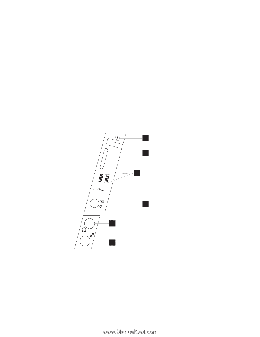
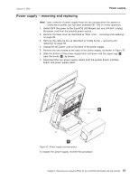
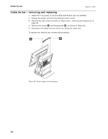
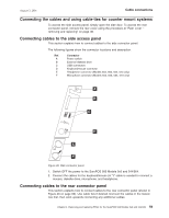
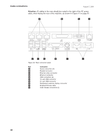
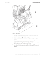
August 3, 2006 Cable connections Connecting the cables and using cable-ties for counter mount systems To access the side access panel, simply open the side door. To access the rear connector panel, remove the rear cover using the procedure at "Rear cover - removing and replacing" on page 38. Connecting cables to the side access panel This section explains how to connect cables to the side connector panel. The following figures show the connector locations and description. Ref. Connector A Power switch B External diskette drive C USB connectors D Keyboard/mouse connector E Headphone connector (Models 553, 563, 564, 573 only) F Microphone connector (Models 553, 563, 564, 573 only) A B C D E F Figure 39. Side connector panel 1. Switch OFF the power to the SurePOS 500 Models 5x3 and 544/564. 2. Connect the cables for the keyboard/mouse (A "Y" cable is needed to connect a mouse), diskette drive, microphone, and headphone. Connecting cables to the rear connector panel This section explains how to connect cables to the rear connector panel (shown in Figure 40 on page 60). Use cable ties if desired. Connect the cables in the lowest row first, then work upwards connecting any additional cables. Chapter 4. Removing and replacing FRUs for the SurePOS 500 Models 5x3 and 544/564 59
-
 1
1 -
2
-
3
-
4
-
5
-
6
-
7
-
8
-
9
-
10
-
11
-
12
-
13
-
14
-
15
-
16
-
17
-
18
-
19
-
20
-
21
-
22
-
23
-
24
-
25
-
26
-
27
-
28
-
29
-
30
-
31
-
32
-
33
-
34
-
35
-
36
-
37
-
38
-
39
-
40
-
41
-
42
-
43
-
44
-
45
-
46
-
47
-
48
-
49
-
50
-
51
-
52
-
53
-
54
-
55
-
56
-
57
-
58
-
59
-
60
-
61
-
62
-
63
-
64
-
65
-
66
-
67
-
68
-
69
-
70
-
71
-
72
-
73
-
74
-
75
-
76
-
77
-
78
-
79
-
 80
80 -
 81
81 -
 82
82 -
 83
83 -
 84
84 -
 85
85 -
 86
86 -
 87
87 -
 88
88 -
 89
89 -
 90
90 -
91
-
92
-
93
-
94
-
95
-
96
-
97
-
98
-
99
-
100
-
101
-
102
-
103
-
104
-
105
-
106
-
107
-
108
-
109
-
110
-
111
-
112
-
113
-
114
-
115
-
116
-
117
-
118
-
119
-
120
-
121
-
122
-
123
-
124
-
125
-
126
-
127
-
128
-
129
-
130
-
131
-
132
-
133
-
134
-
135
-
136
-
137
-
138
-
139
-
140
-
141
-
142
-
143
-
144
-
145
-
146
-
147
-
148
-
149
-
150
-
151
-
152
-
153
-
154
-
155
-
156
-
157
-
158
-
159
-
160
-
161
-
162
-
163
-
164
-
165
-
166
-
167
-
168
-
169
-
170
-
171
-
172
-
173
-
174
-
175
-
176
-
177
-
178
-
179
-
180
-
181
-
182
-
183
-
184
-
185
-
186
-
187
-
188
-
189
-
190
-
191
-
192
-
193
-
194
-
195
-
196
-
197
-
198
-
199
-
200
-
201
-
202
-
203
-
204
-
205
-
206
-
207
-
208
-
209
-
210
-
211
-
212
-
213
-
214
-
215
-
216
-
217
-
218
-
219
-
220
-
221
-
222
-
223
-
224
-
225
-
226
-
227
-
228
-
229
-
230
-
231
-
232
-
233
-
234
-
235
-
236
-
237
-
238
-
239
-
240
-
241
-
242
-
243
-
244
-
245
-
246
-
247
-
248
-
249
-
250
-
251
-
252
-
253
-
254
-
255
-
256
-
257
-
258
 |
 |