IBM 4840-544 Service Guide - Page 149
SureMark, printer, replacing
 |
View all IBM 4840-544 manuals
Add to My Manuals
Save this manual to your list of manuals |
Page 149 highlights
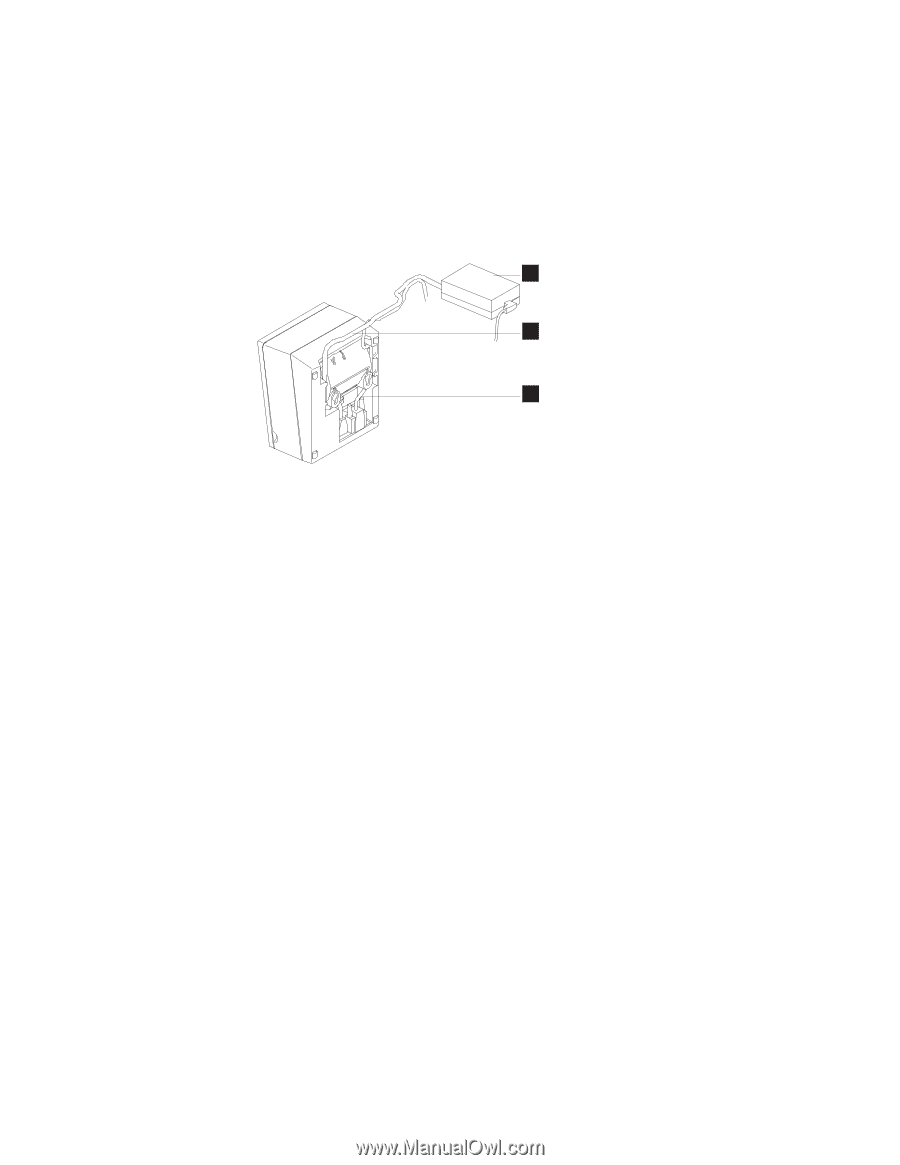
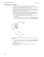
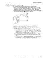
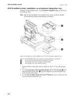
August 3, 2006 4610 SureMark printer 4610 SureMark printer - replacing Use the following instructions for replacing the 4610 SureMark printer: 1. Check the printer RS-232 mode switch settings, which is near the rear cable connections. See E in Figure 97 on page 121 for switch location. For switch settings, see the IBM 4610 SureMark Point-of-Sale Printers User's Guide. 2. Connect and route the RS-232 communication cable or Powered USB cable B and the power supply cable A as shown in Figure 99. C A B Figure 99. Attaching and routing the signal and power supply cables to the printer. 3. Connect any other signal cables for I/O devices to the correct ports. 4. Go to the appropriate 4610 SureMark printer installation procedure for your SurePOS 500 Models 5x3 and 544/564 configuration: a. To install a free standing 4610 SureMark printer, route the cables to the rear connector panel on the SurePOS 500 Models 5x3 and 544/564 system unit, passing it through the hole in the base, and plug it into one of the three standard serial ports, as shown in Figure 40 on page 60. b. To install the printer on a non-keyboard integration tray, go to "4610 SureMark printer installation on a non-keyboard integration tray" on page 124. c. To install the printer on a keyboard integration tray, go to "4610 SureMark printer installation on a keyboard integration tray" on page 126. Chapter 4. Removing and replacing FRUs for the SurePOS 500 Models 5x3 and 544/564 123
-
 1
1 -
2
-
3
-
4
-
5
-
6
-
7
-
8
-
9
-
10
-
11
-
12
-
13
-
14
-
15
-
16
-
17
-
18
-
19
-
20
-
21
-
22
-
23
-
24
-
25
-
26
-
27
-
28
-
29
-
30
-
31
-
32
-
33
-
34
-
35
-
36
-
37
-
38
-
39
-
40
-
41
-
42
-
43
-
44
-
45
-
46
-
47
-
48
-
49
-
50
-
51
-
52
-
53
-
54
-
55
-
56
-
57
-
58
-
59
-
60
-
61
-
62
-
63
-
64
-
65
-
66
-
67
-
68
-
69
-
70
-
71
-
72
-
73
-
74
-
75
-
76
-
77
-
78
-
79
-
80
-
81
-
82
-
83
-
84
-
85
-
86
-
87
-
88
-
89
-
90
-
91
-
92
-
93
-
94
-
95
-
96
-
97
-
98
-
99
-
100
-
101
-
102
-
103
-
104
-
105
-
106
-
107
-
108
-
109
-
110
-
111
-
112
-
113
-
114
-
115
-
116
-
117
-
118
-
119
-
120
-
121
-
122
-
123
-
124
-
125
-
126
-
127
-
128
-
129
-
130
-
131
-
132
-
133
-
134
-
135
-
136
-
137
-
138
-
139
-
140
-
141
-
142
-
143
-
 144
144 -
 145
145 -
 146
146 -
 147
147 -
 148
148 -
 149
149 -
 150
150 -
 151
151 -
 152
152 -
 153
153 -
 154
154 -
155
-
156
-
157
-
158
-
159
-
160
-
161
-
162
-
163
-
164
-
165
-
166
-
167
-
168
-
169
-
170
-
171
-
172
-
173
-
174
-
175
-
176
-
177
-
178
-
179
-
180
-
181
-
182
-
183
-
184
-
185
-
186
-
187
-
188
-
189
-
190
-
191
-
192
-
193
-
194
-
195
-
196
-
197
-
198
-
199
-
200
-
201
-
202
-
203
-
204
-
205
-
206
-
207
-
208
-
209
-
210
-
211
-
212
-
213
-
214
-
215
-
216
-
217
-
218
-
219
-
220
-
221
-
222
-
223
-
224
-
225
-
226
-
227
-
228
-
229
-
230
-
231
-
232
-
233
-
234
-
235
-
236
-
237
-
238
-
239
-
240
-
241
-
242
-
243
-
244
-
245
-
246
-
247
-
248
-
249
-
250
-
251
-
252
-
253
-
254
-
255
-
256
-
257
-
258
 |
 |