IBM 4840-544 Service Guide - Page 141
Removing, replacing, components, latch, sensor, assembly
 |
View all IBM 4840-544 manuals
Add to My Manuals
Save this manual to your list of manuals |
Page 141 highlights
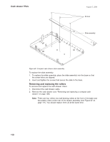
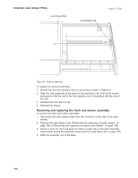
August 3, 2006 Spring Retainer Cash Drawer Propulsion Spring Common cash drawer FRUs Pawl Latches Latch Plate Bracket Cam Latches Pawl Screws Card Assembly Cam Cam Spring Figure 92. Cash-drawer latch and sensor assembly To replace the latch and sensor assembly: 1. Slide the assembly into the base from the front and align it with the slots in the base. Push the assembly to the rear until it locks into place. 2. Make sure that the latching mechanism is unlatched. 3. Reinstall the drawer. 4. Reconnect the cash-drawer cable. Removing and replacing components of the latch and sensor assembly To remove the individual components of the latch and sensor assembly: 1. Disconnect the cash-drawer cable. 2. Remove the cash drawer (see "Removing and replacing a full-size drawer" on page 105 or "Removing and replacing a compact cash drawer" on page 108). 3. Remove the latch assembly (see "Removing and replacing the latch and sensor assembly" on page 114). 4. Remove the cash-drawer propulsion spring by pushing the spring retainer back, and then slide the spring up and out of its mounting slots (see Figure 92). 5. Remove the latch plate bracket by removing the screw in the cam pivot post and the screw in the pawl pivot post (see Figure 92). 6. Remove the cam spring by lifting the ends of the small posts on the cam and the pawl (see Figure 92). 7. Spread apart the two pawl latches that hold the pawl on the pivot post, while lifting the pawl off the post (see Figure 92). 8. Spread apart the two cam latches that hold the cam on the pivot post, while lifting the cam off the post (see Figure 92). 9. Remove the three screws that retain the card assembly and remove the card assembly (see Figure 92). Chapter 4. Removing and replacing FRUs for the SurePOS 500 Models 5x3 and 544/564 115
-
 1
1 -
2
-
3
-
4
-
5
-
6
-
7
-
8
-
9
-
10
-
11
-
12
-
13
-
14
-
15
-
16
-
17
-
18
-
19
-
20
-
21
-
22
-
23
-
24
-
25
-
26
-
27
-
28
-
29
-
30
-
31
-
32
-
33
-
34
-
35
-
36
-
37
-
38
-
39
-
40
-
41
-
42
-
43
-
44
-
45
-
46
-
47
-
48
-
49
-
50
-
51
-
52
-
53
-
54
-
55
-
56
-
57
-
58
-
59
-
60
-
61
-
62
-
63
-
64
-
65
-
66
-
67
-
68
-
69
-
70
-
71
-
72
-
73
-
74
-
75
-
76
-
77
-
78
-
79
-
80
-
81
-
82
-
83
-
84
-
85
-
86
-
87
-
88
-
89
-
90
-
91
-
92
-
93
-
94
-
95
-
96
-
97
-
98
-
99
-
100
-
101
-
102
-
103
-
104
-
105
-
106
-
107
-
108
-
109
-
110
-
111
-
112
-
113
-
114
-
115
-
116
-
117
-
118
-
119
-
120
-
121
-
122
-
123
-
124
-
125
-
126
-
127
-
128
-
129
-
130
-
131
-
132
-
133
-
134
-
135
-
 136
136 -
 137
137 -
 138
138 -
 139
139 -
 140
140 -
 141
141 -
 142
142 -
 143
143 -
 144
144 -
 145
145 -
 146
146 -
147
-
148
-
149
-
150
-
151
-
152
-
153
-
154
-
155
-
156
-
157
-
158
-
159
-
160
-
161
-
162
-
163
-
164
-
165
-
166
-
167
-
168
-
169
-
170
-
171
-
172
-
173
-
174
-
175
-
176
-
177
-
178
-
179
-
180
-
181
-
182
-
183
-
184
-
185
-
186
-
187
-
188
-
189
-
190
-
191
-
192
-
193
-
194
-
195
-
196
-
197
-
198
-
199
-
200
-
201
-
202
-
203
-
204
-
205
-
206
-
207
-
208
-
209
-
210
-
211
-
212
-
213
-
214
-
215
-
216
-
217
-
218
-
219
-
220
-
221
-
222
-
223
-
224
-
225
-
226
-
227
-
228
-
229
-
230
-
231
-
232
-
233
-
234
-
235
-
236
-
237
-
238
-
239
-
240
-
241
-
242
-
243
-
244
-
245
-
246
-
247
-
248
-
249
-
250
-
251
-
252
-
253
-
254
-
255
-
256
-
257
-
258
 |
 |
