IBM 4840-544 Service Guide - Page 142
Removing, replacing, keylock, insert, blank
 |
View all IBM 4840-544 manuals
Add to My Manuals
Save this manual to your list of manuals |
Page 142 highlights
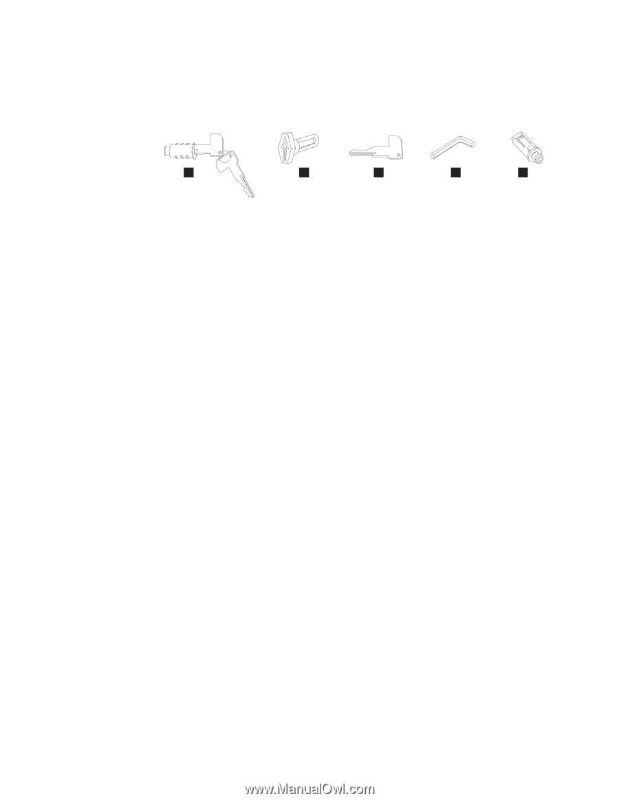
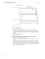
Common cash drawer FRUs August 3, 2006 To replace the components of the latch and sensor assembly, reverse this procedure. Removing and replacing the keylock insert A B C D E Figure 93. Lock accessories A Lock insert and keys. B Aligner. This tool is used to ensure that the slot at the bottom of the lock cylinder aligns with the lock insert being installed. For the cash drawer, the arrow on the aligner should point up. (The arrow points in different directions for other types of devices.) C Brass installation-removal key. D Blank lock installation handle. E Blank lock insert. To remove the keylock insert: 1. The lock must be in the unlocked position. 2. Insert the brass installation-removal key fully into the lock until it clicks into place. 3. Pivot the brass key slightly downward while pulling the lock insert out of the cylinder until the insert is disengaged from the cylinder. Note: The brass key and the lock insert come out of the lock cylinder together. Pressing downward or sideways on the brass key as you pull makes it easier for the lock insert to come out along with the brass key. 4. Remove the brass key. To replace the keylock insert: 1. The lock insert fits all the way into the lock cylinder only when the slot in the bottom of the cylinder and the lug on the end of the insert are aligned. If necessary, insert the aligner tool (see Figure 93) into the lock cylinder and rotate it until you feel it engage the slot at the bottom of the cylinder; then turn the aligner tool until the arrow points up. 2. Remove the key that came with the new lock insert. 3. Push the brass installation-removal key into the lock insert. Be sure the key is fully inserted. 4. With the brass installation-removal key still in the lock insert, push the lock insert fully into the lock cylinder. 5. While holding the lock insert in place with your finger, remove the installation-removal key. 6. Test the lock using the keys that came with the insert to be sure that the lock operates correctly. Removing and replacing the blank lock insert To remove the blank lock insert: 116
-
 1
1 -
2
-
3
-
4
-
5
-
6
-
7
-
8
-
9
-
10
-
11
-
12
-
13
-
14
-
15
-
16
-
17
-
18
-
19
-
20
-
21
-
22
-
23
-
24
-
25
-
26
-
27
-
28
-
29
-
30
-
31
-
32
-
33
-
34
-
35
-
36
-
37
-
38
-
39
-
40
-
41
-
42
-
43
-
44
-
45
-
46
-
47
-
48
-
49
-
50
-
51
-
52
-
53
-
54
-
55
-
56
-
57
-
58
-
59
-
60
-
61
-
62
-
63
-
64
-
65
-
66
-
67
-
68
-
69
-
70
-
71
-
72
-
73
-
74
-
75
-
76
-
77
-
78
-
79
-
80
-
81
-
82
-
83
-
84
-
85
-
86
-
87
-
88
-
89
-
90
-
91
-
92
-
93
-
94
-
95
-
96
-
97
-
98
-
99
-
100
-
101
-
102
-
103
-
104
-
105
-
106
-
107
-
108
-
109
-
110
-
111
-
112
-
113
-
114
-
115
-
116
-
117
-
118
-
119
-
120
-
121
-
122
-
123
-
124
-
125
-
126
-
127
-
128
-
129
-
130
-
131
-
132
-
133
-
134
-
135
-
136
-
 137
137 -
 138
138 -
 139
139 -
 140
140 -
 141
141 -
 142
142 -
 143
143 -
 144
144 -
 145
145 -
 146
146 -
 147
147 -
148
-
149
-
150
-
151
-
152
-
153
-
154
-
155
-
156
-
157
-
158
-
159
-
160
-
161
-
162
-
163
-
164
-
165
-
166
-
167
-
168
-
169
-
170
-
171
-
172
-
173
-
174
-
175
-
176
-
177
-
178
-
179
-
180
-
181
-
182
-
183
-
184
-
185
-
186
-
187
-
188
-
189
-
190
-
191
-
192
-
193
-
194
-
195
-
196
-
197
-
198
-
199
-
200
-
201
-
202
-
203
-
204
-
205
-
206
-
207
-
208
-
209
-
210
-
211
-
212
-
213
-
214
-
215
-
216
-
217
-
218
-
219
-
220
-
221
-
222
-
223
-
224
-
225
-
226
-
227
-
228
-
229
-
230
-
231
-
232
-
233
-
234
-
235
-
236
-
237
-
238
-
239
-
240
-
241
-
242
-
243
-
244
-
245
-
246
-
247
-
248
-
249
-
250
-
251
-
252
-
253
-
254
-
255
-
256
-
257
-
258
 |
 |