IBM 4840-544 Service Guide - Page 118
Full-size, keyboard, integration
 |
View all IBM 4840-544 manuals
Add to My Manuals
Save this manual to your list of manuals |
Page 118 highlights
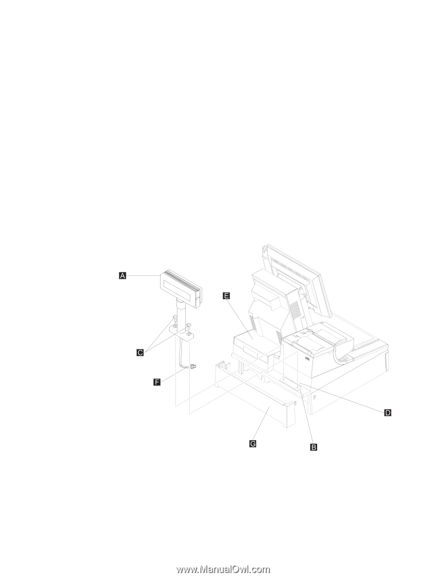
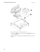
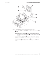
Full-size keyboard integration tray August 3, 2006 The following procedures tell you how to remove the different devices on the full-size keyboard-integration tray: 1. Prepare the SurePOS 500 Models 5x3 and 544/564 for disassembly by performing the necessary steps for the devices that are being removed: a. Switch OFF the power to the SurePOS 500 Models 5x3 and 544/564. Unplug the system power cord from the external power source. b. Remove the filler panels necessary to gain access to the rear cover. c. Remove the rear cover as described at "Rear cover - removing and replacing" on page 38 and unplug the power cord from the system unit at the power supply. d. Remove the cash-drawer rear cover. Push in the two buttons located at the rear sides of the cash drawer and then pull the cash-drawer rear cover back and off. 2. To remove the distributed customer display, perform the following steps: a. Unplug the distributed character display cable from the SurePOS 500 Models 5x3 and 544/564 rear connector panel, as shown in Figure 40 on page 60. b. Unroute the distributed character display cable F to enable the distributed character display to be removed, as shown in Figure 68. Figure 68. Remove the distributed character display from a full-size integration tray c. Remove the distributed character display A by removing the two thumbscrews C from mounting post B . Lift up on the display and pull cable F up through slot D . d. For information on disassembling the distributed character display or APA, go to "Distributed customer display - disassembling" on page 118. 3. To remove the keyboard, perform the following steps: 92
-
 1
1 -
2
-
3
-
4
-
5
-
6
-
7
-
8
-
9
-
10
-
11
-
12
-
13
-
14
-
15
-
16
-
17
-
18
-
19
-
20
-
21
-
22
-
23
-
24
-
25
-
26
-
27
-
28
-
29
-
30
-
31
-
32
-
33
-
34
-
35
-
36
-
37
-
38
-
39
-
40
-
41
-
42
-
43
-
44
-
45
-
46
-
47
-
48
-
49
-
50
-
51
-
52
-
53
-
54
-
55
-
56
-
57
-
58
-
59
-
60
-
61
-
62
-
63
-
64
-
65
-
66
-
67
-
68
-
69
-
70
-
71
-
72
-
73
-
74
-
75
-
76
-
77
-
78
-
79
-
80
-
81
-
82
-
83
-
84
-
85
-
86
-
87
-
88
-
89
-
90
-
91
-
92
-
93
-
94
-
95
-
96
-
97
-
98
-
99
-
100
-
101
-
102
-
103
-
104
-
105
-
106
-
107
-
108
-
109
-
110
-
111
-
112
-
 113
113 -
 114
114 -
 115
115 -
 116
116 -
 117
117 -
 118
118 -
 119
119 -
 120
120 -
 121
121 -
 122
122 -
 123
123 -
124
-
125
-
126
-
127
-
128
-
129
-
130
-
131
-
132
-
133
-
134
-
135
-
136
-
137
-
138
-
139
-
140
-
141
-
142
-
143
-
144
-
145
-
146
-
147
-
148
-
149
-
150
-
151
-
152
-
153
-
154
-
155
-
156
-
157
-
158
-
159
-
160
-
161
-
162
-
163
-
164
-
165
-
166
-
167
-
168
-
169
-
170
-
171
-
172
-
173
-
174
-
175
-
176
-
177
-
178
-
179
-
180
-
181
-
182
-
183
-
184
-
185
-
186
-
187
-
188
-
189
-
190
-
191
-
192
-
193
-
194
-
195
-
196
-
197
-
198
-
199
-
200
-
201
-
202
-
203
-
204
-
205
-
206
-
207
-
208
-
209
-
210
-
211
-
212
-
213
-
214
-
215
-
216
-
217
-
218
-
219
-
220
-
221
-
222
-
223
-
224
-
225
-
226
-
227
-
228
-
229
-
230
-
231
-
232
-
233
-
234
-
235
-
236
-
237
-
238
-
239
-
240
-
241
-
242
-
243
-
244
-
245
-
246
-
247
-
248
-
249
-
250
-
251
-
252
-
253
-
254
-
255
-
256
-
257
-
258
 |
 |