IBM 4840-544 Service Guide - Page 78
cables, removing, replacing
 |
View all IBM 4840-544 manuals
Add to My Manuals
Save this manual to your list of manuals |
Page 78 highlights
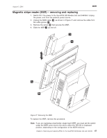
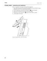
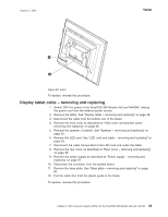
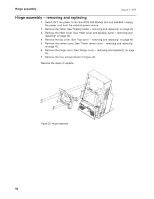
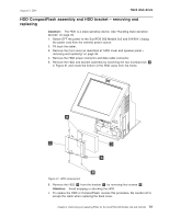
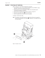
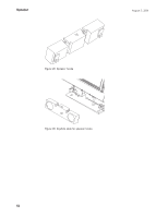
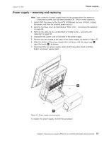
Hard disk drive August 3, 2006 8. Power ON the system and use the Setup Utility to verify that the system recognizes the new HDD. Note: If the system fails to recognize the new HDD, verify that all HDD cables are seated and then verify that the address jumper is correctly installed. If the HDD requires that a jumper is recognized as Drive 0, the correct position is indicated on a label on the top of the HDD. HDD cables - removing and replacing 1. Switch OFF the power to the SurePOS 500 Models 5x3 and 544/564. Unplug the power cord from the external power source. See Figure 31 on page 51. 2. Remove the front cover as described at "HDD cover and speaker panel - removing and replacing" on page 36. 3. Remove the HDD power connector and data cable connector from the side of the HDD. 4. Remove the HDD and bracket. See "HDD CompactFlash assembly and HDD bracket - removing and replacing" on page 51. 5. Cut any cable ties on the cables. 6. To remove the data cable, you must remove the system board. See "System board - removing and replacing" on page 65. 7. Disconnect the power cable from the power supply and the data cable from the system board. 8. Remove the base plate. See "Base plate - removing and replacing" on page 80. 9. Pull the power cable free from the plastic guide in the frame. To replace, reverse this procedure. HDD fan - removing and replacing Note: The HDD fan FRU kit might include the fan mounting bracket. It is not required that you replace the mounting bracket when replacing a defective fan. 1. Switch OFF the power to the SurePOS 500 Models 5x3 and 544/564. Unplug the power cord from the external power source. See Figure 31 on page 51. 2. Remove the following covers. v HDD cover (see "HDD cover and speaker panel - removing and replacing" on page 36) v top cover (see "Top cover - removing and replacing" on page 40) v tower center cover (see "Tower center cover - removing and replacing" on page 45) v hinge cover (see "Hinge cover - removing and replacing" on page 46) 3. Disconnect the HDD fan power connector. 4. Remove the two screws that hold the fan to the mounting bracket. To replace, reverse this procedure. 52
-
 1
1 -
2
-
3
-
4
-
5
-
6
-
7
-
8
-
9
-
10
-
11
-
12
-
13
-
14
-
15
-
16
-
17
-
18
-
19
-
20
-
21
-
22
-
23
-
24
-
25
-
26
-
27
-
28
-
29
-
30
-
31
-
32
-
33
-
34
-
35
-
36
-
37
-
38
-
39
-
40
-
41
-
42
-
43
-
44
-
45
-
46
-
47
-
48
-
49
-
50
-
51
-
52
-
53
-
54
-
55
-
56
-
57
-
58
-
59
-
60
-
61
-
62
-
63
-
64
-
65
-
66
-
67
-
68
-
69
-
70
-
71
-
72
-
 73
73 -
 74
74 -
 75
75 -
 76
76 -
 77
77 -
 78
78 -
 79
79 -
 80
80 -
 81
81 -
 82
82 -
 83
83 -
84
-
85
-
86
-
87
-
88
-
89
-
90
-
91
-
92
-
93
-
94
-
95
-
96
-
97
-
98
-
99
-
100
-
101
-
102
-
103
-
104
-
105
-
106
-
107
-
108
-
109
-
110
-
111
-
112
-
113
-
114
-
115
-
116
-
117
-
118
-
119
-
120
-
121
-
122
-
123
-
124
-
125
-
126
-
127
-
128
-
129
-
130
-
131
-
132
-
133
-
134
-
135
-
136
-
137
-
138
-
139
-
140
-
141
-
142
-
143
-
144
-
145
-
146
-
147
-
148
-
149
-
150
-
151
-
152
-
153
-
154
-
155
-
156
-
157
-
158
-
159
-
160
-
161
-
162
-
163
-
164
-
165
-
166
-
167
-
168
-
169
-
170
-
171
-
172
-
173
-
174
-
175
-
176
-
177
-
178
-
179
-
180
-
181
-
182
-
183
-
184
-
185
-
186
-
187
-
188
-
189
-
190
-
191
-
192
-
193
-
194
-
195
-
196
-
197
-
198
-
199
-
200
-
201
-
202
-
203
-
204
-
205
-
206
-
207
-
208
-
209
-
210
-
211
-
212
-
213
-
214
-
215
-
216
-
217
-
218
-
219
-
220
-
221
-
222
-
223
-
224
-
225
-
226
-
227
-
228
-
229
-
230
-
231
-
232
-
233
-
234
-
235
-
236
-
237
-
238
-
239
-
240
-
241
-
242
-
243
-
244
-
245
-
246
-
247
-
248
-
249
-
250
-
251
-
252
-
253
-
254
-
255
-
256
-
257
-
258
 |
 |
